e.blog

主にUnity/UE周りのことについてまとめていきます

Unityでクリッピング平面を実装する

概要

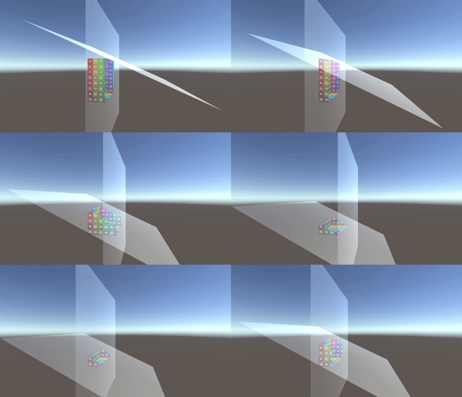
今作っているARアプリでクリッピング平面を作る必要が出てきたのでそのメモです。

動作サンプル↓ f:id:edo_m18:20180508201124g:plain

動画サンプルで動かしたものはGitHubで公開しています。

ちなみに、クリッピング平面自体の説明は以前Qiitaに書いたのでそちらをご覧ください。
今回書くのはARアプリで使用したUnityでのクリッピング平面の実装メモです。

qiita.com

実装

今回、Unityで実装するに当たってクリッピング平面の位置や方向などはC#側で計算し、それをシェーダに渡す形で実装しました。

まずはC#コードを。

C#コード

using System.Collections;
using System.Collections.Generic;
using UnityEngine;

public class ClippingPlanes : MonoBehaviour
{
    [SerializeField]
    private Transform[] _clippingPlanes;

    private Material _material;

    private void Awake()
    {
        _material = GetComponent<MeshRenderer>().material;
    }

    private void Update()
    {
        Vector4[] planes = new Vector4[_clippingPlanes.Length];
        Matrix4x4 viewMatrix = Camera.main.worldToCameraMatrix;

        for (int i = 0; i < planes.Length; i++)
        {
            Vector3 viewUp = viewMatrix.MultiplyVector(_clippingPlanes[i].up);
            Vector3 viewPos = viewMatrix.MultiplyPoint(_clippingPlanes[i].position);
            float distance = Vector3.Dot(viewUp, viewPos);
            planes[i] = new Vector4(viewUp.x, viewUp.y, viewUp.z, distance);
        }

        _material.SetVectorArray("_ClippingPlanes", planes);
    }
}

上記は、平面の方向と距離を算出するコードです。
大事なポイントは3つ。

  1. worldToCameraMatrixがビューマトリクス
  2. worldToCameraMatrix.MultiplyVectorで平面方向をビュー座標に変換
  3. worldToCameraMatrix.MultiplyPointで平面位置を変換、方向ベクトルに射影して距離を得る

です。

そして以下のコードで「平面の方向と距離」をVector4としてシェーダに渡します。

planes[i] = new Vector4(viewUp.x, viewUp.y, viewUp.z, distance);

// ... 中略

_material.SetVectorArray("_ClippingPlanes", planes);

ちなみに、複数プレーンでクリッピングができるようにしてみたのでプレーンの方向と距離は配列でシェーダに渡しています。

シェーダでは_ClippingPlanesを利用してクリッピングを実行します。
シェーダコードは以下です。

Shader "Unlit/ClippingPlane"
{
    Properties
    {
        [Toggle] _Positive("Cull Positive", Float) = 1
        _PlaneCount("Plane count", Range(0, 10)) = 0
        _MainTex ("Texture", 2D) = "white" {}
    }
    SubShader
    {
        Tags { "RenderType"="Opaque" }
        LOD 100

        Pass
        {
            Cull Off

            CGPROGRAM
            #pragma vertex vert
            #pragma fragment frag
            #pragma multi_compile_fog
            
            #include "UnityCG.cginc"

            struct appdata
            {
                float4 vertex : POSITION;
                float2 uv : TEXCOORD0;
            };

            struct v2f
            {
                float2 uv : TEXCOORD0;
                UNITY_FOG_COORDS(1)
                float4 viewVertex : TEXCOORD2;
                float4 vertex : SV_POSITION;
            };

            sampler2D _MainTex;
            float4 _MainTex_ST;
            float _Positive;
            uniform float _PlaneCount;
            uniform float4 _ClippingPlanes[10];
            
            v2f vert (appdata v)
            {
                v2f o;
                o.vertex = UnityObjectToClipPos(v.vertex);
                o.uv = TRANSFORM_TEX(v.uv, _MainTex);
                UNITY_TRANSFER_FOG(o,o.vertex);
                o.viewVertex = mul(UNITY_MATRIX_MV, v.vertex);
                return o;
            }
            
            fixed4 frag (v2f i) : SV_Target
            {
                int count = int(_PlaneCount);
                for (int idx = 0; idx < count; idx++)
                {
                    float4 plane = _ClippingPlanes[idx];
                    if (_Positive == 0)
                    {
                        if (dot(plane.xyz, i.viewVertex.xyz) > plane.w)
                        {
                            discard;
                        }
                    }
                    else 
                    {
                        if (dot(plane.xyz, i.viewVertex.xyz) < plane.w)
                        {
                            discard;
                        }
                    }
                }

                fixed4 col = tex2D(_MainTex, i.uv);
                UNITY_APPLY_FOG(i.fogCoord, col);
                return col;
            }
            ENDCG
        }
    }
}

最後に判定部分。
C#から送られてきた、ビュー座標空間での方向と距離を元にビュー座標空間上でのフラグメントの位置を内積を使って計算し、距離が平面より遠かったらクリッピングdiscard)する、という処理です。

また、今回のサンプルでは_PlaneCountで平面の数を指定できるようにしています。
というのもシェーダでは配列を可変にできないため予め領域を確保しておく必要があります。

なので、外部からいくつの平面が渡ってくるかを指定できるようにしている、というわけです。
今回はサンプルなのでひとまず最大10平面まで受け取れるようにしています。

実際問題、クリッピングを実行したい、という平面の数はそこまで多くならないと思います。
もし多数必要になったらテクスチャにして渡すなどある程度工夫が必要でしょう。

が、今回はあくまでクリッピング平面の実装メモなのでそのあたりは適当です。

余談

ちなみにこの判定は面白くて、どこかの質問サイトで見たのが、キャラクターが地面に接地しているか、の判定にまさにこの仕組みを利用していて、なぜこれで接地が判定できるのですか? という質問がありました。

方向と距離を渡して、あとは内積結果と比較するだけで判定が済むので圧倒的な省コストで判定できることになります。
ロジックとしては覚えておくと色々役に立ちそうです。

余談2

ちなみに、これとは別視点で実装した「異空間から現れてた」ような演出をするシェーダについて過去に書いたので興味があったら読んでみてください。

edom18.hateblo.jp

UnityのCompute ShaderでCurl Noiseを実装(衝突判定編)

概要

今回は「衝突判定編」です。
前回の「流体編」の続編です。

edom18.hateblo.jp


さて、今回は論文で発表されたカールノイズの『衝突判定』について書きたいと思います。

実際に動いている動画↓


本題

カールノイズによる流体のような移動表現については前回書きました。
論文によると、これに加えて剛体などの境界を考慮した動きを実現できるそう。

境界による干渉(論文より抜粋)

境界による干渉について、論文では以下のように書かれています。
原文と、それに対する翻訳(Google翻訳+若干の意訳)を併記します。


境界(Boundaries)

Consider a motionless solid object in the flow. The boundary condition viscous flow must satisfy is \vec{v} = 0.

流れの中に動かないオブジェクトを考えてみる。
その境界条件粘性流は\vec{v} = 0を満たさなければならない。

This can be achieved simply by modulating the potential down to zero with a smoothed step function of distance, so that all the partial derivatives (and hence the curl) of the new potential are zero at the boundary.

これは、距離の平滑化された段階関数を用いてポテンシャルをゼロに変調することでシンプルに達成できる。
つまり、新しいポテンシャルのすべての偏微分(したがってカール)境界でゼロになる。

Of more interest in animation is the inviscid boundary condition, \vec{v} \cdot \vec{n} = 0, requiring that the component of velocity normal to the boundary is zero.

アニメーションで関心があるのは、非粘性境界条件(v \cdot n = 0)である。
必要なのは、境界に垂直な速度の成分がゼロであることだ。

allowing the fluid to slip past tangentially but not to flow through a solid. Most turbulent fluids have such small viscosities that this is a more reasonable approximation.

流体が接線方向に滑ることを可能にするが、固体を通して流れないようにする。
ほとんどの乱流は、これがより合理的な近似であるような小さな粘性を有する。

In two dimensions, note that our velocity field is just the 90◦ rotation of the gradient ∇ψ: if we want the velocity field to be tangent to the boundary, we need the gradient to be perpendicular to the boundary.

二次元では、速度場は勾配(\nabla \psi)の90°回転に過ぎないことに注意。
速度場を境界線に接したい場合は、境界線に対して垂直な勾配が必要だ。

This happens precisely when the boundary is an isocontour of ψ, i.e. when ψ has some constant value along the boundary.

これは、境界がψの等値であるとき、つまりψが境界に沿ってある一定の値を有するときに正確に起こる。

We can achieve this without eliminating the gradient altogether by modulating ψ with a ramp through zero based on distance to the closest boundary point.

最も近い境界点までの、距離に基いてゼロを通るRampでψを変調することによって、勾配を完全になくすことなくこれを達成できる。


ψ_{constrained}(\vec{x}) = ramp\biggl(\frac{d(\vec{x})}{d_0}\biggr) ψ(\vec{x}) ... (3)

where d(\vec{x}) is the distance to all solid boundaries and d_0 is the width of the modified region—when using noise with length scale L, it makes sense to set d_0 = L. We use the following smooth ramp:

d(\vec{x})は、すべてのソリッド境界までの距離であり、d_0は修正された領域の幅である。
長さスケールLのノイズを使用する場合、d_0 = Lに設定することは理にかなっている。
次の、平滑化Ramp関数を利用する:


\begin{eqnarray}
ramp(r){=}
\begin{cases}
1 &amp; : r \geq 1 \\
\frac{15}{8}r - \frac{10}{8}{r}^3 + \frac{3}{8}{r}^5 &amp;: 1 > r > -1 \\
-1 &amp; : r \leq -1
\end{cases}
\end{eqnarray}
... (4)

In three dimensions things are a little more complicated.

3次元の場合はもう少し複雑だ。


α = \biggl|ramp\biggl(\frac{d(\vec{x})}{d_0}\biggr)\biggr|

\vec{n} be the normal to the boundary at the closest point to \vec{x}, we use

nx に最も近い点の境界の法線である。
したがって、次の式を使う。


\vec{ψ}_{constrained}(\vec{x}) = α\vec{ψ} (\vec{x}) + (1 − α) \hat{n} (\hat{n} \cdot \vec{ψ} (\vec{x})) ... (5)

That is, we ramp down the tangential component of \vec{ψ} near the boundary, but leave the normal component unchanged. This can be proven to give a tangential velocity field at smooth object boundaries, using the fact that \vec{n} is the gradient of signed distance from the boundary (hence its curl vanishes).

つまり、\vec{\psi}の接線成分を境界付近で下降(ramp down)させるが、通常の成分は変化させない。
これは、nが境界からの符号付き距離の勾配であるという事実を利用して、滑らかなオブジェクト境界で接線方向の速度場を与えることが証明される。
(したがってそのカールは消える)

Unfortunately, the normal field may be discontinuous along the medial axis of the geometry: na¨ıvely using equation (5) can result in spikes when we take the curl, particularly near sharp edges.

残念なことに、通常のフィールドは、ジオメトリの内側軸に沿って不連続である可能性がある。
式(5)を使用すると、カールを取るとき、特に鋭いエッジ付近でスパイクが発生する可能性がある。

This isn’t a problem for equation (3) since the distance field is Lipschitz continuous, which is adequate for our purposes.

これは、距離場がLipschitz連続であるため、式(3)の問題ではない。
これは、目的に対して適切である。

Thus within distance d_0 of edges flagged as sharp in the system we default to (3), i.e. drop the normal component.

したがって、システム内でシャープとフラグ立てられたエッジの距離d0内では、デフォルトで(3)になる。
すなわち、通常の成分を落とす。


さて、初見ではなんのこっちゃですが、(自分の浅い理解では)要するに、境界付近では接線方向にのみ速度を持たせてやることで、そちらに流れていくよね、ということを言いたいのだと思います。

そのことを示す式が以下です。


\vec{ψ}_{constrained}(\vec{x}) = α\vec{ψ} (\vec{x}) + (1 − α) \hat{n} (\hat{n} \cdot \vec{ψ} (\vec{x})) ... (5)

constrained(拘束)が示すように、境界付近での速度の方向を拘束し、流れを変えることを表す式です。

もう少し具体的に見てみましょう。
式の右辺を見ると、\vec{\psi}(\vec{x})に対してなにやら計算しています。

この\psiはポテンシャル、つまりカールノイズの計算部分です。
その得られた速度ベクトルに対してなにやら計算しているわけです。

式を少し簡単にしてみると、(\vec{\psi}(\vec{x})Pと置きます)


αP + (1 - α)P

ということです。

つまり、なんらかの係数に応じて徐々にそちらのベクトルを採用する、いわゆる線形補間的な計算ですね。

ただ、右側に置かれているほうはもう少し複雑で、正確には以下です。


(1 − α) \hat{n} (\hat{n} \cdot \vec{ψ} (\vec{x}))

ただ、これも分解して考えると、いわゆる「法線方向ベクトルにどれだけ沿っているか」の計算です。
一般的な計算に書き直してみると、


\hat{n}(\hat{n} \cdot \vec{x})

ですね。

コードで表してみる

さて、上記の部分をコードで表したのが以下になります。

境界の法線を計算する

式では、境界付近の法線を利用しています。
そして法線の計算は以下のようになります。

// 勾配(gradient)を計算する
// 基本的な考えは偏微分が法線ベクトルとなることを利用している?
float3 ComputeGradient(float3 p)
{
    const float e = 0.01f;

    // 偏微分するため、各軸の微小値を計算する
    const float3 dx = float3(e, 0, 0);
    const float3 dy = float3(0, e, 0);
    const float3 dz = float3(0, 0, e);

    float d = SampleDistance(p);
    float dfdx = SampleDistance(p + dx) - d;
    float dfdy = SampleDistance(p + dy) - d;
    float dfdz = SampleDistance(p + dz) - d;

    return normalize(float3(dfdx, dfdy, dfdz));
}

// 計算点から、障害物への距離を計算する
float SampleDistance(float3 p)
{
    float3 u = _SphereParam.xyz - p;
    float d = length(u);
    return d - _SphereParam.w;
}

なぜ偏微分したらそれが法線ベクトルになるのかについては以下を参照。

mathtrain.jp

また、距離関数については、(今回は)単純なSphereのみとしているので、比較的シンプルな式で距離計算が出来ています。
その他の距離関数については、こちらのサイトを参照ください。

modeling with distance functions

そして、ポテンシャルの計算を行っているコードが以下。

// α = ramp(d(x)/d0)
// ψ_constrainted(x) = αψ(x) + (1 - α)n(n・ψ(x))
float3 SamplePotential(float3 pos, float time)
{
    float3 normal = ComputeGradient(pos);
    float distance = SampleDistance(pos);

    float3 psi = float3(0, 0, 0);

    // 高さに応じて乱流の度合いを変化させる(上にいくほど拡散するように)
    float heightFactor = Ramp((pos.y - _PlumeBase) / _PlumeHeight);
    for (int i = 0; i < 3; i++)
    {
        float alpha = Ramp(abs(distance) / _NoiseScales[i]);

        float3 s = pos / _NoiseScales[i];

        float3 psi_i = Constraint(Pnoise(s), normal, alpha);
        psi += psi_i * heightFactor * _NoiseGain[i];
    }

    float3 risingForce = _SphereParam.xyz - pos;
    risingForce = float3(-risingForce.z, 0, risingForce.x);

    // ringの半径?
    // XZ平面の中心からの半径? RingRadius?
    float rr = sqrt(pos.x * pos.x + pos.z * pos.z);
    float temp = sqr(rr - _RingRadius) + sqr(rr + _RingRadius) + _RingFalloff;
    float invSecond = 1.0 / _RingPerSecond;
    float ringY = _PlumeCeiling;
    float alpha = Ramp(abs(distance) / _RingRadius);

    // 「煙の柱(Plume)」の下端以下になるまで繰り返す
    while (ringY > _PlumeBase)
    {
        // ringの位置とパーティクルのYの差分
        float ry = pos.y - ringY;

        float b = temp + sqr(ry);
        float rmag = _RingMagnitude / b;

        float3 rpsi = rmag * risingForce;
        psi += Constraint(rpsi, normal, alpha);
        ringY -= _RingSpeed * invSecond;
    }

    return psi;
}

なお、上記コードの乱流生成部分は以下の記事を参考にさせてもらいました。

prideout.net

カールノイズを実装したコンピュートシェーダ全文はこちら↓

github.com

論文翻訳メモ

さて、最後に、論文を理解するにあたってちょいちょい(Google翻訳などを利用しながら)翻訳していったものがあるので、せっかくなのでメモとして残しておこうと思います。

※ 注意! いくらかは自分の意訳部分があるので、完全な翻訳ではありません。

論文はこちら(PDF)


​速度は、ポテンシャル(ベクトル場)(\vec{ψ})に対して回転(curl)をかけたものとして得られる。


\vec{v} = \nabla \times ψ

カールされたベクトル場は自動的にダイバージェンスフリーとなる。

A classic vector calculus identity is that the curl of a smooth potential is automatically divergence-free


\nabla \cdot \nabla \times = 0

よって、


\nabla \cdot \vec{v} = 0

パーリンノイズN(\vec{x})を使ってベクトル場を形成する。
2Dの場合は、単純にψ=N

To construct a randomly varying velocity field we use Perlin noise N(\vec{x}) in our potential. In 2D, [tex:]\psi = N].

3Dの場合は、3要素(ベクトル)が必要となるが、同じノイズ関数を、明らかに大きなオフセットをかけた入力ベクトルを用いて表現する。
普段は、いくつかの異なったスケールを使ったオクターブノイズを乱流の形成のために使う。

In 3D we need three components for the potential: three apparently uncorrelated noise functions (a vector \vec{N}(\vec{x})) do the job, which in practice can be the same noise function evaluated at large offsets.


\psi(x, t) = A(x)\psi_T(x, t) + ramp\biggl(\frac{d(x)}{d_L}\biggr)\psi_L(x)

3Dの場合は、速度ノイズの接線成分のみ、ゼロに減少する。

In 3D, only tangential components of vector noise are ramped down.

シーン内のオブジェクトからゼロに減衰するか、または煙の列の高さに応じて変化させる。

decay to zero away from objects in the scene, or changing it according to the height in a column of smoke.

速度場 A(\vec{x})\vec{v}(\vec{x}) はもはやdivergence-freeを与えないが、それにカールのトリックで成す。

While simply modulating the velocity field A(\vec{x})\vec{v}(\vec{x}) no longer gives a divergnce-free field, modulating the potential, \vec{v} = \nabla \times (A(\vec{x})\psi(\vec{x})), does the trick.

他のポテンシャル(Other Potentials)

これまでは、動かない境界線に対するノイズだけを構築してきた。
もちろん、既存のプリミティブのフローを速度場に使って、よりリッチな機能を実現することもできる。
そして、ポテンシャルをより高めることができる。

So far we have only constructed noise that respects unmoving solid boundaries. While of course we can superimpose existing flow primitives on the velocity field for richer capabilities, we can also do more with the potential itself.

線形速度Vと角速度ωを持つRigidbodyに対応するポテンシャルを導出することはシンプルにできる。

It is simple to derive a potential corresponding to a rigid body motion with linear velocity \vec{V} and angular velocity \vec{ω} :


\vec{\psi}_{rigid}(\vec{x}) = \vec{V} \times (\vec{x} − \vec{x_0}) + \frac{{R}^2 - {|| \vec{x} − \vec{x_0} ||}^2}{2} \vec{ω}

ここで、\vec{x_0}は任意の参照点であり、Rは任意の参照レベルを表す。

where {x_0} is an arbitrary reference point and R is an arbitrary reference level.

Note:
同じvに対応する無限に多くのポテンシャルが常に存在することに気をつける。
スカラー場の勾配だけが異なるふたつのポテンシャルは、同じカールを有する。

Note that there are always infinitely many potentials corresponding to the same \vec{v}: any two potentials which differ by only the gradient of some scalar field have exactly the same curl.

動くRigidbodyの境界条件を満たすように修正したポテンシャル\vec{\psi}を仮定する。
まず、物体の表面上速度の法線成分をゼロにするために方程式(5)を使用し、\vec{\psi_0}を与える。
次に、x_0を剛体の中心として選択した式(6)を使用し、オブジェクトからゼロに滑らかにブレンドする。
Rブレンド領域の半径とすると、ブレンドされた回転項が単調に0に落ちる)

Suppose we have a potential \vec{ψ} we wish to modify to respect boundary conditions on a moving rigid object. First we use equation (5) to zero out the normal component of velocity on the object’s surface, giving \vec{ψ_0}. Then we use equation (6) with x_0 chosen, say, as the center of the rigid body, smoothly blend it to zero away from the object (choosing R to be the radius of the blend region, so that the blended rotational term drops monotonically to zero),

それを加えて


\vec{ψ} (\vec{x}) = \vec{ψ}_0 + A(\vec{x})\vec{ψ}_{rigid}(\vec{x})

を得る。

例えば、各剛体への逆二乗距離に基づくブレンド関数A(\vec{x})の実験を行った。

We have experimented, for example, with a blending function A(\vec{x}) based on inverse squared distance to each rigid body.

剛体の境界では、速度は剛体モーションと、表面に接するベクトル場の合計となる。
これは構成上、非粘性境界条件を尊重する。

Note that at the boundary of the rigid object, the velocity is the sum of the rigid motion and a vector field tangent to the surface: by construction this respects the inviscid boundary condition.

単一のボディにてついては参照点は任意だが、複数のボディがある場合は同じ参照点を使用してブレンドをよりよくするのに役立つ。
特に、すべてのボディが同じ剛体モーションで動いている場合は、そのポテンシャルを合わせてブレンドを完璧にしたいと考えている。

While for a single body the reference point is arbitrary, if we have multiple bodies it can help to use the same reference point to make the blend better. In particular, if all bodies are moving with the same rigid motion, then of course we want their potentials to match up to make the blend perfect.

変形する物体の周りの流れ場はよりトリッキーである。
閉じた変形表面の場合、もしボディがその体積を保持しなければ不可能である。
したがって、将来の作業のためにそれは残しておく。

Flow fields around deforming bodies are trickier. For a closed deforming surface, it may even be impossible—if the body doesn’t conserve its volume—and thus we leave that for future work.

いくつかのプリミティブな渦(Vortex)は、\vec{x}位置の角速度\vec{ω}、半径R、および平滑化フォールオフ関数を有する単純なパーティクルを含む。

Some vortex primitives include a simple vortex particle at \vec{x_0} with angular velocity \vec{ω} , radius R, and smooth fall-off function f :


\vec{\psi}_{vort}(\vec{x}) = f\Biggl(\frac{||\vec{x} − \vec{x_0}||}{R}\Biggr) \frac{{R}^2 − ||\vec{x} − \vec{x_0}||^2}{2} \vec{ω} ... (7)

そして、スモーク・リングやプルーム(Plumes)に役立つ、単純な渦カーブ:

and a simple vortex curve, useful for smoke rings and plumes:


\vec{\psi}_{curve}(\vec{x}) = f\Biggl(\frac{||\vec{x} − \vec{x_C}||}{R}\Biggr) \frac{{R}^2 − ||\vec{x} − \vec{x_C}||^2}{2} \vec{ω_C} ... (8)

\vec{x_C}\vec{x}までの、曲線上の最も近い点であり、\vec{ω_C}は角速度(曲線に接する)である。

他の興味深いフロー構造も、剛体運動式を念頭に置いて同様に作成することができる。

where \vec{x_C} is the closest point on the curve to \vec{x}, and \vec{ω} C is the angular velocity (tangent to the curve). Other interesting flow structures can be similarly created with the rigid motion formulas in mind.

備考メモ

論文に書かれている備考部分に対するメモです。(あくまで個人的な解釈です)
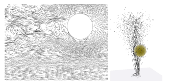
f:id:edo_m18:20180111134000p:plain
↑論文に添えられていた図

左手側は、剛体の背後に乱流を起こしたもの。右手側は、流体を後ろに押し出したあと渦輪を設定したもの。(あってる?)

どちらのケースも、乱流ノイズの各オクターブは、ジオメトリに対してスケールに適した方法で調整される。


\psi_t(x) = \sum_i a_i ramp\left(\frac{d(x)}{d_i}\right) N\left(\frac{x}{d_i}, \frac{t}{d_i}\right)

そして、障害物の背後にのみ生成した乱流に平滑化された振幅関数を乗算する。
これを、基礎の層流(lamninar(ラミナ))に加える。これも、境界付近でスムーズにゼロにランプされる。

※ 流体の流れは2つに分けられ、流体部分が秩序正しく流れる場合を層流と呼び、不規則に混合しながら流れる場合を乱流と呼ぶ。
出典: https://www.weblio.jp/content/laminar+flow


\psi(x, t) = A(x) \psi_T(x, t) + ramp\left(\frac{d(x)}{d_L}\right) \psi_L(x)

個人的見解

以下は、論文を読んでいくにあたって、記号など「こういう意味かなー」と思ったことのメモです。
記号や単語の意味を類推して読んでいくと意外とすっと頭に入ってくることもあるので。

\psi_T(x)が、乱流(Trubulent)を表す式。(なのでT
それを、ジオメトリに応じてAdjustする変数a
これが「乱流」部分になるので、それを、基礎層流(Laminar Flow)に加える、ということになる。
(という意味かな?)

そして、基礎層流を表すのが


ramp\left(\frac{d(x)}{d_L}\right) \psi_L(x)

の式。

仮にこれをLと置き、さらに乱流をTと置くと、最後の式は


\psi(x, t) = A(x) T + L

と書ける。

このA(x)が、文章で書かれている「We then multiply by a smooth AMPLITUDE function」のことだと思う。

ただ、平滑化された振幅関数ってどう表現するのだろう・・。ひとまず適当にSinとか掛けておけばいいんだろうか。
なんとなく、Sinを使った値を加算してみたら煙が立ち上る感じに見えたので、多分そんな感じなんだと思うw

その他、役立ちそうなリンク

prideout.net

catlikecoding.com

github.com

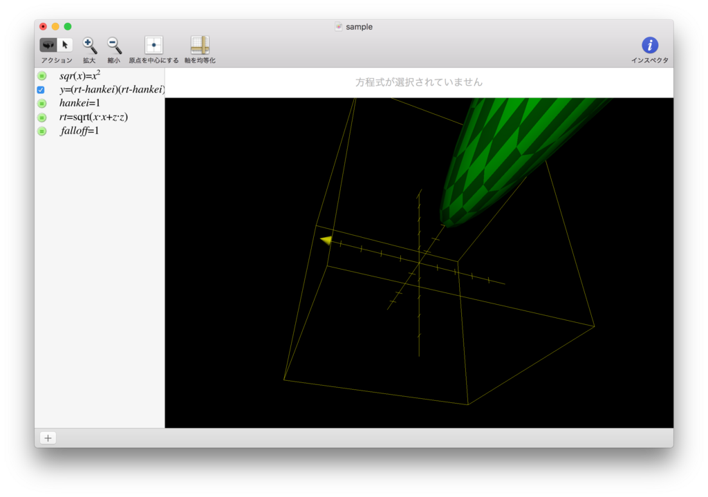
リンクではありませんが、MacにはGrapherというアプリが標準でついていて、以下のキャプチャのように、数式を入れるとそれを可視化してくれる、というものがあります。

数式だけだと一体なにをしているんだ? となることが多いですが、視覚化されると「ああ、なるほど。こういう形を求めているのだな」と分かることが少なくないので、利用して色々な数式を視覚化してみることをオススメします。
f:id:edo_m18:20171210134609p:plain

TransformクラスのTransform**** / InverseTransform****系メソッドのメモ

以前、Qiitaで書いていた記事の移植です。
Inverse系も追加したのでこちらに移動しました。

概要

TransformPointTransformVectorTransformDirectionがそれぞれなにをやってくれているのか、ピンと来てなかったので、どういう処理をしたら同じ結果が得られるのか書いてみたのでメモ。

まぁやってることはシンプルに、モデル行列掛けているだけだけど、その後の処理で平行移動を無効化したり正規化したり、といったことをしている。方向だけを取りたい、みたいなときに使う。
なにやってるか分からないと気持ち悪かったので書いてみた、完全にメモですw

Transform****系メソッド

// ----------------------------------------------------------------------------
// TransformPoint
// 意味: 通常のモデル行列を掛けたポイントを得る
Vector3 point = Vector3.one;
Vector3 newPoint1 = transform.TransformPoint(point);

Vector4 v = new Vector4(point.x, point.y, point.z, 1f);
Vector3 newPoint2 = transform.localToWorldMatrix * v;

// ↓Vector4作らないで済むのでこちらのほうが便利
// Vector3 newPoint2 = transform.localToWorldMatrix.MultiplyPoint(point);

// ----------------------------------------------------------------------------
// TransformVector
// 意味: 回転を適用したのちに、平行移動を無効化したベクトルを得る
Vector3 vector = new Vector3(0, 1.5f, 0);
Vector3 newVector1 = transform.TransformVector(vector);

Vector4 v = new Vector4(vector.x, vector.y, vector.z, 1f);
Vector3 newVector2 = (transform.localToWorldMatrix * v) - transform.position;

// ↓Vector4作らないで済むのでこちらのほうが便利
// Vector3 newVector2 = transform.localToWorldMatrix.MultiplyVector(vector);

// ----------------------------------------------------------------------------
// TransformDirection
// 意味: 回転を適用したのちに、平行移動を無効化し正規化したベクトルを得る
Vector3 direction = Vector3.up;
Vector3 newDirection1 = transform.TransformDirection(direction);

Vector4 v = new Vector4(direction.x, direction.y, direction.z, 1f);
Vector3 newDirection2 = ((transform.localToWorldMatrix * v) - transform.position).normalized;

// ↓Vector4作らないで済むのでこちらのほうが便利
// Vector3 newDirection2 = transform.localToWorldMatrix.MultiplyVector(direction);

InverseTransform****系メソッド

// ----------------------------------------------------------------------------
// InverseTransformPoint
// 意味: ワールド座標からローカル座標へ変換する

Vector3 newPoint1 = transform.InverseTransformPoint(_v);

Matrix4x4 m = transform.worldToLocalMatrix;
Vector4 p = new Vector4(_v.x, _v.y, _v.z, 1f);
Vector3 newPoint2 = m * p;


// ----------------------------------------------------------------------------
// InverseTransformVector
// 意味: 指定したベクトルの方向のみ、ワールド座標からローカル座標へ変換する

Vector3 newdir1 = transform.InverseTransformVector(_v);

Matrix4x4 m = transform.worldToLocalMatrix;
Vector4 c0 = m.GetColumn(0);
Vector4 c1 = m.GetColumn(1);
Vector4 c2 = m.GetColumn(2);
Vector4 c3 = new Vector4(0, 0, 0, 1f);
Matrix4x4 newM = new Matrix4x4(c0, c1, c2, c3);
newM = newM.inverse.transpose;

Vector4 p = new Vector4(_v.x, _v.y, _v.z, 1f);
Vector3 newdir2 = newM * p;

// ↓内容的には以下でまかなえる
// Vector3 newdir2 = transform.worldToLocalMatrix.MultiplyVector(_v);


// ----------------------------------------------------------------------------
// InverseTransformDirection
//
// ※ InverseTransformVectorの正規化した単位ベクトルを得るのかと思いきや、InverseTransformVectorと同じだったので割愛

解説

Inverse系のVector処理はやや複雑です。抜粋するとコードは以下。

Matrix4x4 m = transform.worldToLocalMatrix;
Vector4 c0 = m.GetColumn(0);
Vector4 c1 = m.GetColumn(1);
Vector4 c2 = m.GetColumn(2);
Vector4 c3 = new Vector4(0, 0, 0, 1f);
Matrix4x4 newM = new Matrix4x4(c0, c1, c2, c3);
newM = newM.inverse.transpose;

取り出した、ワールドからローカルへの変換行列をさらに分解して新しい行列を生成しています。
ここでやっていることは方向のみのベクトルを扱う関係で平行移動部分を除去し、移動なしの行列に変換しています。

そして最後に、逆転置行列にするためにnewM = newM.inverse.transpose;としています。

なぜ逆転置行列なのか。
それには理由があります。詳細については以下の記事がとても詳しいのでそちらを御覧ください。

raytracing.hatenablog.com

言葉で説明している箇所を引用させていただくと、

頂点について、モデル座標系からワールド座標系に移すときには何らかの変換行列を使って変換する。
しかし、頂点に対して作用する行列と同じものを法線に対して作用させてもうまくいかない。 まず、平行移動成分を除去しなければならない。法線は向きのみの量なので平行移動は関係ないからである。
回転移動成分についてはそのまま使うことが出来る。
拡大縮小などのスケーリング成分については、たとえば各頂点をX軸方向に3倍にする場合、法線はX軸方向に1/3倍にする必要がある。(最終的に正規化して長さは1にする)

これらの各要素を考慮しつつ法線を適切に変換するための行列を求めるには、頂点の変換行列の逆転置行列を求めればよい、ということが知られている。

ということ。
実際にベクトルを書いてみると分かりますが、スケールを掛けると方向が異なった方向を向いてしまいます。
しかし今回の求めるべきベクトルは方向を適切に変換することにあります。

なので上記のように「逆転置行列」を使う必要がある、というわけです。

TransformのLookAtをUnity APIを使わずに書く

概要

仕事でLookAtを、Unity APIを使わずに書くことがあったのでメモ。

実行した結果。ちゃんとCubeを注視し続けます。
f:id:edo_m18:20180418015908g:plain

サンプルコード

実装したサンプルコードは以下。

このスクリプトをカメラに貼り付けて、ターゲットを指定すると常にそれを視界に捉えた状態になります。

using System.Collections;
using System.Collections.Generic;
using UnityEngine;

public class LookAtSample : MonoBehaviour
{
    [SerializeField]
    private Transform _target;
    
    private void Update()
    {
        LookAt(_target.position);
    }

    private void LookAt(Vector3 target)
    {
        Vector3 z = (target - transform.position).normalized;
        Vector3 x = Vector3.Cross(Vector3.up, z).normalized;
        Vector3 y = Vector3.Cross(z, x).normalized;

        Matrix4x4 m = Matrix4x4.identity;
        m[0, 0] = x.x; m[0, 1] = y.x; m[0, 2] = z.x;
        m[1, 0] = x.y; m[1, 1] = y.y; m[1, 2] = z.y;
        m[2, 0] = x.z; m[2, 1] = y.z; m[2, 2] = z.z;

        Quaternion rot = GetRotation(m);
        transform.rotation = rot;
    }

    private Quaternion GetRotation(Matrix4x4 m)
    {
        float[] elem = new float[4];
        elem[0] = m.m00 - m.m11 - m.m22 + 1.0f;
        elem[1] = -m.m00 + m.m11 - m.m22 + 1.0f;
        elem[2] = -m.m00 - m.m11 + m.m22 + 1.0f;
        elem[3] = m.m00 + m.m11 + m.m22 + 1.0f;

        int biggestIdx = 0;
        for (int i = 0; i < elem.Length; i++)
        {
            if (elem[i] > elem[biggestIdx])
            {
                biggestIdx = i;
            }
        }

        if (elem[biggestIdx] < 0)
        {
            Debug.Log("Wrong matrix.");
            return new Quaternion();
        }

        float[] q = new float[4];
        float v = Mathf.Sqrt(elem[biggestIdx]) * 0.5f;
        q[biggestIdx] = v;
        float mult = 0.25f / v;

        switch (biggestIdx)
        {
            case 0:
                q[1] = (m.m10 + m.m01) * mult;
                q[2] = (m.m02 + m.m20) * mult;
                q[3] = (m.m21 - m.m12) * mult;
                break;
            case 1:
                q[0] = (m.m10 + m.m01) * mult;
                q[2] = (m.m21 + m.m12) * mult;
                q[3] = (m.m02 - m.m20) * mult;
                break;
            case 2:
                q[0] = (m.m02 + m.m20) * mult;
                q[1] = (m.m21 + m.m12) * mult;
                q[3] = (m.m10 - m.m01) * mult;
                break;
            case 3:
                q[0] = (m.m21 - m.m12) * mult;
                q[1] = (m.m02 - m.m20) * mult;
                q[2] = (m.m10 - m.m01) * mult;
                break;
        }

        return new Quaternion(q[0], q[1], q[2], q[3]);
    }
}

LookAtの行列を作る

LookAtは結局のところ、ターゲットに向く「回転」を作ることと同義です。

上のコードでやっていることはシンプルです。
「向かせたい方向のベクトル」と「空方向のベクトル」から、外積を使ってX軸を割り出します。
(空方向と垂直なベクトルはX軸ですよね)

そして向かせたい方向ベクトルがZ軸となるわけなので、結果として、割り出したX軸と向かせたいベクトルとの外積を取ることで最終的な「上方向」のベクトルを得ることができます。
(「上」が空方向とは限らない)

そうやって求めた3軸の各要素を元に行列を作ります。
なぜこれが「LookAt」に相当するのか。

(x, y, z)(1, 1, 1)のときを考えてみましょう。
該当のコードは以下です。

private void LookAt(Vector3 target)
{
    Vector3 z = (target - transform.position).normalized;
    Vector3 x = Vector3.Cross(Vector3.up, z).normalized;
    Vector3 y = Vector3.Cross(z, x).normalized;

    Matrix4x4 m = Matrix4x4.identity;
    m[0, 0] = x.x; m[0, 1] = y.x; m[0, 2] = z.x;
    m[1, 0] = x.y; m[1, 1] = y.y; m[1, 2] = z.y;
    m[2, 0] = x.z; m[2, 1] = y.z; m[2, 2] = z.z;

    Quaternion rot = GetRotation(m);
    transform.rotation = rot;
}

そして今作った行列をそのベクトル(1, 1, 1)に適用してみます。
Unityの行列は列オーダーなので、ベクトルを右から掛けることで計算します。
つまり、

 \begin{vmatrix}
x.x &y.x &z.x \\
x.y &y.y &z.y \\
x.z &y.z &z.z \\
\end{vmatrix}\times
\begin{vmatrix}
1 \\
1 \\
1 \\
\end{vmatrix}=
\begin{vmatrix}
x.x &y.x & z.x
\end{vmatrix}

となって、回転後の値になっているのが分かるかと思います。

回転行列からクォータニオンを計算する

さて、無事に回転行列が作れましたが、Unityでは回転をクォータニオンで扱っています。
そのため、求めた回転行列はそのまま使えません。なので、クォータニオンに変換する必要があります。

回転行列からクォータニオンへの変換は、マルペケさんのこちらの記事(その58 やっぱり欲しい回転行列⇔クォータニオン相互変換)を参考にさせていただきました。

コード部分は以下です。

private Quaternion GetRotation(Matrix4x4 m)
{
    float[] elem = new float[4];
    elem[0] = m.m00 - m.m11 - m.m22 + 1.0f;
    elem[1] = -m.m00 + m.m11 - m.m22 + 1.0f;
    elem[2] = -m.m00 - m.m11 + m.m22 + 1.0f;
    elem[3] = m.m00 + m.m11 + m.m22 + 1.0f;

    int biggestIdx = 0;
    for (int i = 0; i < elem.Length; i++)
    {
        if (elem[i] > elem[biggestIdx])
        {
            biggestIdx = i;
        }
    }

    if (elem[biggestIdx] < 0)
    {
        Debug.Log("Wrong matrix.");
        return new Quaternion();
    }

    float[] q = new float[4];
    float v = Mathf.Sqrt(elem[biggestIdx]) * 0.5f;
    q[biggestIdx] = v;
    float mult = 0.25f / v;

    switch (biggestIdx)
    {
        case 0:
            q[1] = (m.m10 + m.m01) * mult;
            q[2] = (m.m02 + m.m20) * mult;
            q[3] = (m.m21 - m.m12) * mult;
            break;
        case 1:
            q[0] = (m.m10 + m.m01) * mult;
            q[2] = (m.m21 + m.m12) * mult;
            q[3] = (m.m02 - m.m20) * mult;
            break;
        case 2:
            q[0] = (m.m02 + m.m20) * mult;
            q[1] = (m.m21 + m.m12) * mult;
            q[3] = (m.m10 - m.m01) * mult;
            break;
        case 3:
            q[0] = (m.m21 - m.m12) * mult;
            q[1] = (m.m02 - m.m20) * mult;
            q[2] = (m.m10 - m.m01) * mult;
            break;
    }

    return new Quaternion(q[0], q[1], q[2], q[3]);
}

詳細についてはマルペケさんの記事をご覧ください。

ざっくり概要だけを書くと、回転行列の各要素はクォータニオンから回転行列に変換する際に「どの要素を使うか」で求めることができます。
マルペケさんで書かれている行列を引用させていただくと、以下のようになります。


\begin{vmatrix}
1 - 2y^2 - 2z^2 &2xy + 2wz &2xz - 2wy &0 \\
2xy - 2wz &1 - 2x^2 - 2z^2 &2yz + 2wx &0 \\
2xz + 2wy &2yz - 2wx &1 - 2x^2 - 2y^2 &0 \\
0 &0 &0 &1
\end{vmatrix}

ここで使われているx, y, z, wクォータニオンの各成分です。

そして、この値を組み合わせることによって目的のx, y, z, wを求める、というのが目標です。
例えば、以下の回転行列の要素を組み合わせることで値を取り出します。


m_{11} + m_{22} + m_{33} = 3 - 4(x^2 + y^2 + z^2)  \\
= 3 - 4(n_x^2 + n_y^2 + n_z^2) \sin^2 \theta ' \\
= 3 - 4(1 - \cos^2 \theta ' \\
= 4w^2 - 1

となります。
ここで、 \theta ' = \frac{\theta}{2}なので、wの式に直すと以下のようになります。


w = \frac{\sqrt{m_{11} + m_{22} + m_{33} + 1}}{2}

他の値も同様にして計算していきます。
これ以外にも色々考慮しないとならないことがありますが、詳細についてはマルペケさんの記事をご覧ください。

こうして求めたクォータニオンを、該当オブジェクトのrotationに設定することで、冒頭の画像のようにLookAtが完成します。

フリーハンドで描いた図形をポリゴン分割する

概要

フリーハンドで平面に描いた形に図形を形成するのをやりたかったので、頂点群からポリゴンを形成する処理について書きたいと思います。

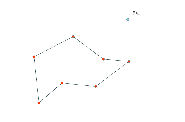
こんな感じで、適当に打った点からポリゴンを形成します↓

点群からポリゴンを形成する

まず必要になるのが、点群からポリゴンを形成する処理です。

実装についてはこちらの記事(Javaゲーム制作記 任意多角形の三角形分割)を参考にさせていただきました。

ちなみに、記事中に、さらに元となった記事へのリンクが書いてありましたがリンク切れしてました。
おそらく元となった記事はこちらだと思います↓

sonson.jp

任意の点群からポリゴンを形成する

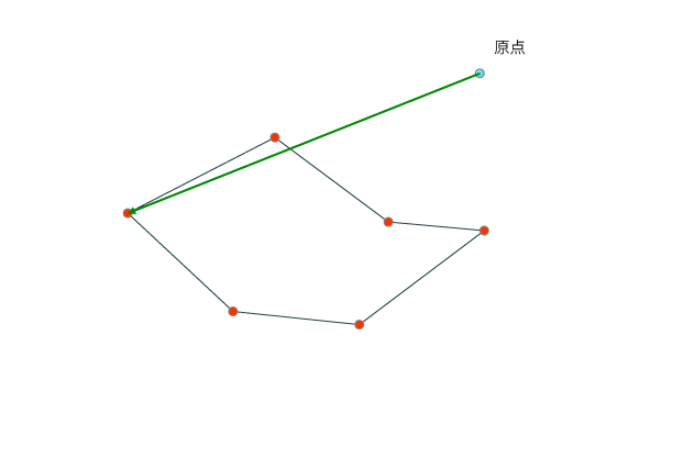
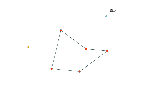
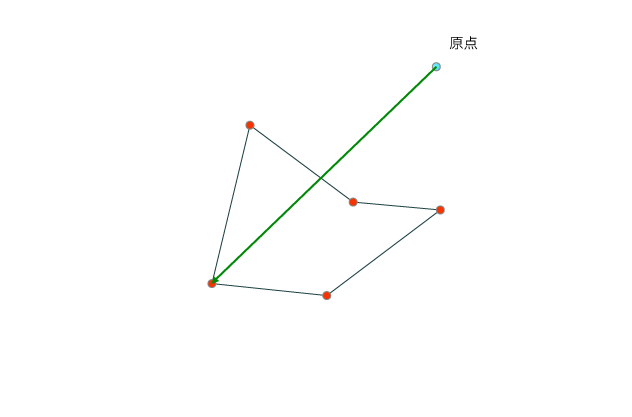
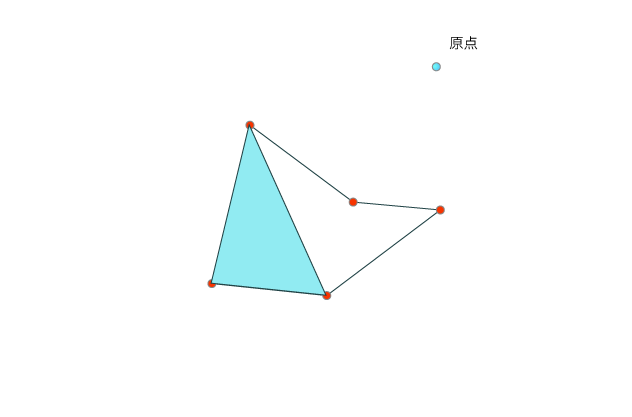
点群からポリゴンを形成するには、当然ですが点群が囲む任意多角形をポリゴンとして三角形に分割していく作業が必要になります。

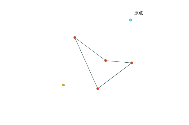
大まかに流れを書くと以下のようになります。

  1. 点群を得る
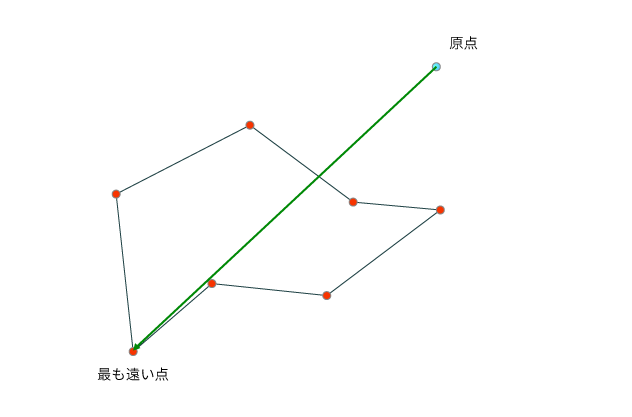
  2. 点群の中で、任意の点(※1)から一番遠い点を見つける
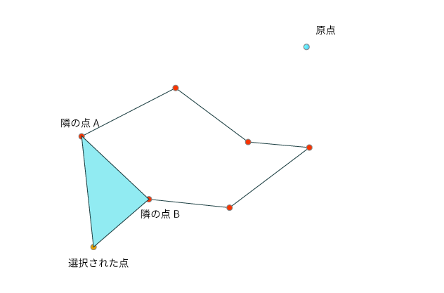
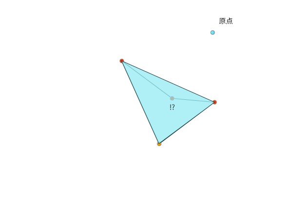
  3. (2)で見つかった点とその両隣の点で三角形を作る
  4. このとき、(2)の点と両隣の点から成る線が作る角度が180度を超えていないことを確認する(※2)
  5. (3)で形成した三角形の中に、点郡の他の点が含まれていないことを確認する
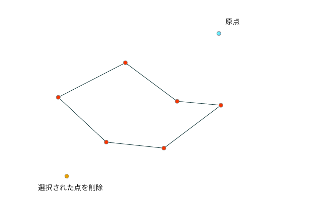
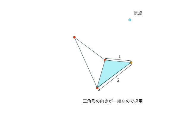
  6. (5)で内包している点がなかったら、それを分割された三角形として採用し、(2)で見つかった点を点群リストから除外する
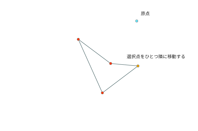
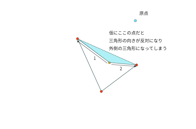
  7. もし(5)の工程で内包する点が見つかった場合は三角形が構成できないので、ひとつ隣の点を採用点に変更し、もう一度(5)の処理を行う。その際、確認した三角形の向きを保持しておく(※3)
  8. (5)の処理を行い、見つかった三角形と、(7)で保持していた三角形の向きをチェックし、異なった方向だった場合はまた隣の点に移動して(5)の処理を繰り返す
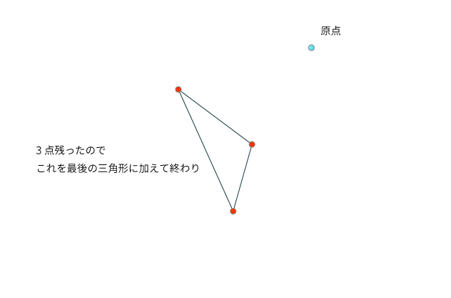
  9. 以後、点群が残り3点(三角形が構成できる最後の点群)になるまで繰り返す

※1 ... 任意の点なのでどこでも構いません。原点などが採用しやすいでしょう。
※2 ... もし超えている場合、見つけた点よりも遠い点が存在するため判定がおかしい。
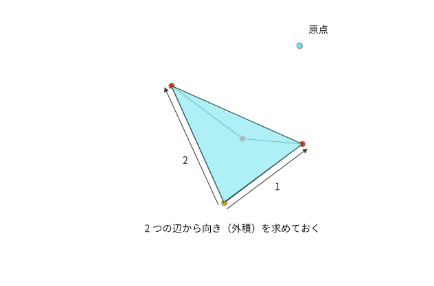
※3 ... 向きをチェックする理由は、多角形の点の構成によっては外側の三角形が見つかる可能性があるため(図解で後述します)

以上の手順を繰り返すことで、点群を複数の三角形に分割し、冒頭の画像のように任意の多角形をポリゴンに分解することができるようになります。

・・・と、文章だとなんのこっちゃ、だと思うのでまずは図解してみます。

f:id:edo_m18:20180324231129p:plain f:id:edo_m18:20180324231123p:plain f:id:edo_m18:20180324231218p:plain f:id:edo_m18:20180324231222p:plain f:id:edo_m18:20180324231321p:plain f:id:edo_m18:20180324231324p:plain f:id:edo_m18:20180324231327p:plain f:id:edo_m18:20180324231330p:plain f:id:edo_m18:20180324231337p:plain f:id:edo_m18:20180324231340p:plain f:id:edo_m18:20180324231346p:plain f:id:edo_m18:20180324231349p:plain
作った三角形の中に別の点が含まれてしまっている f:id:edo_m18:20180324231353p:plain
三角形の向きは採用点から次の点を辺1、前の点を辺2として、その外積を使って求める f:id:edo_m18:20180324231356p:plain f:id:edo_m18:20180324231402p:plain f:id:edo_m18:20180324231405p:plain f:id:edo_m18:20180324231408p:plain

以上のような感じで、順々に三角形に分解していき、最後の3頂点になるまでそれを繰り返す、という方法です。
仕組み自体はとてもシンプルですね。

コードで見てみる

今回実装したコードも合わせて載せておきます。
(図解したことをコードにしているだけなので、詳細は割愛します)

using System.Collections;
using System.Collections.Generic;
using UnityEngine;

/// <summary>
/// Draw mesh by clicked points.
/// </summary>
public class DrawMesh : MonoBehaviour
{
    private List<Vector3> _leftVertices = new List<Vector3>();
    private List<Vector3> _triangles = new List<Vector3>();

    private Vector3 _prevDirection = Vector3.zero;

    private bool _isIncluding = false;
    private int _curIndex;
    private int _nextIndex;
    private int _prevIndex;

    private Vector3 CurrentPoint
    {
        get { return _leftVertices[_curIndex]; }
    }
    private Vector3 PreviousPoiont
    {
        get { return _leftVertices[_prevIndex]; }
    }
    private Vector3 NextPoint
    {
        get { return _leftVertices[_nextIndex]; }
    }

    /// <summary>
    /// Clear vertices and triangles.
    /// </summary>
    private void ClearMesh()
    {
        _leftVertices.Clear();
        _triangles.Clear();
    }

    /// <summary>
    /// Create mesh by vertices.
    /// </summary>
    public GameObject CreateMesh(List<Vector3> vertices)
    {
        ClearMesh();

        _leftVertices.AddRange(vertices);

        while (_leftVertices.Count > 3)
        {
            DetecteTriangle();
        }

        _triangles.AddRange(_leftVertices);

        Debug.Log("Done chekcing.");

        Mesh mesh = new Mesh();
        mesh.vertices = _triangles.ToArray();

        int[] indices = new int[_triangles.Count];
        for (int i = 0; i < indices.Length; i ++)
        {
            indices[i] = i;
        }

        mesh.triangles = indices;
        mesh.RecalculateNormals();

        GameObject go = new GameObject("MeshObject", typeof(MeshFilter), typeof(MeshRenderer));

        MeshFilter filter = go.GetComponent<MeshFilter>();
        filter.mesh = mesh;

        return go;
    }

    /// <summary>
    /// Detect triangle from far point.
    /// </summary>
    private void DetecteTriangle()
    {
        if (!_isIncluding)
        {
            FindFarPoint();
        }

        Vector3 a = CurrentPoint;
        Vector3 b = NextPoint;
        Vector3 c = PreviousPoiont;

        Vector3 edge1 = b - a;
        Vector3 edge2 = c - a;

        float angle = Vector3.Angle(edge1, edge2);
        if (angle >= 180)
        {
            Debug.LogError("Something was wrong.");
            return;
        }

        if (IsIncludePoint())
        {
            Debug.Log("Point is including.");

            // try to find other point.
            _isIncluding = true;

            // Store current triangle direction.
            _prevDirection = GetCurrentDirection();

            MoveToNext();

            return;
        }

        _isIncluding = false;

        _triangles.Add(a);
        _triangles.Add(b);
        _triangles.Add(c);

        _leftVertices.RemoveAt(_curIndex);
    }

    /// <summary>
    /// Check to include point in the triangle.
    /// </summary>
    /// <returns></returns>
    private bool IsIncludePoint()
    {
        for (int i = 0; i < _leftVertices.Count; i++)
        {
            // skip if index in detected three points.
            if (i == _curIndex || i == _nextIndex || i == _prevIndex)
            {
                continue;
            }

            if (CheckInPoint(_leftVertices[i]))
            {
                return true;
            }
        }

        return false;
    }

    /// <summary>
    /// Get current triangle direction.
    /// </summary>
    /// <returns>Triagnel direction normal.</returns>
    private Vector3 GetCurrentDirection()
    {
        Vector3 edge1 = (NextPoint - CurrentPoint);
        Vector3 edge2 = (PreviousPoiont - CurrentPoint);

        return Vector3.Cross(edge1, edge2).normalized;
    }

    /// <summary>
    /// Check including point.
    /// </summary>
    /// <param name="target">Target point.</param>
    /// <returns>return true if point is including.</returns>
    private bool CheckInPoint(Vector3 target)
    {
        // Triangle points.
        Vector3[] tp =
        {
            CurrentPoint,
            NextPoint,
            PreviousPoiont,
        };

        Vector3 prevNormal = default(Vector3);
        for (int i = 0; i < tp.Length; i++)
        {
            Vector3 edge1 = (target - tp[i]);
            Vector3 edge2 = (target - tp[(i + 1) % tp.Length]);

            Vector3 normal = Vector3.Cross(edge1, edge2).normalized;

            if (prevNormal == default(Vector3))
            {
                prevNormal = normal;
                continue;
            }

            // If not same direction, the point out of a triangle.
            if (Vector3.Dot(prevNormal, normal) <= 0.99f)
            {
                return false;
            }
        }

        return true;
    }

    /// <summary>
    /// Poition reference move to next.
    /// </summary>
    private void MoveToNext()
    {
        _curIndex = (_curIndex + 1) % _leftVertices.Count;
        _nextIndex = (_curIndex + 1) % _leftVertices.Count;
        _prevIndex = _curIndex - 1 >= 0 ? _curIndex - 1 : _leftVertices.Count - 1;
    }

    /// <summary>
    /// Find far point from origin.
    /// </summary>
    private void FindFarPoint()
    {
        int farIndex = -1;
        float maxDist = float.MinValue;
        for (int i = 0; i < _leftVertices.Count; i++)
        {
            float dist = Vector3.Distance(Vector3.zero, _leftVertices[i]);
            if (dist > maxDist)
            {
                maxDist = dist;
                farIndex = i;
            }
        }

        _curIndex = farIndex;
        _nextIndex = (_curIndex + 1) % _leftVertices.Count;
        _prevIndex = (_curIndex - 1) >= 0 ? _curIndex - 1 : _leftVertices.Count - 1;
    }
}

[2018.05.02追記]

上記コードではポリゴン用の頂点を複製してポリゴン数(x3)と同じだけの頂点を生成していましたが、インデックスを割り当てるように修正したのでそちらのコードも載せておきます。

using System.Collections;
using System.Collections.Generic;
using System.Linq;
using UnityEngine;

/// <summary>
/// Draw mesh by clicked points.
/// </summary>
public class DrawMesh : MonoBehaviour
{
    private List<int> _triangles = new List<int>();
    private List<Vector3> _vertices = new List<Vector3>();
    private Dictionary<int, bool> _verticesBuffer = new Dictionary<int, bool>();

    private Vector3 _prevDirection = Vector3.zero;

    private bool _isIncluding = false;
    private int _curIndex;
    private int _nextIndex;
    private int _prevIndex;

    private Vector3 CurrentPoint
    {
        get { return _vertices[_curIndex]; }
    }
    private Vector3 PreviousPoiont
    {
        get { return _vertices[_prevIndex]; }
    }
    private Vector3 NextPoint
    {
        get { return _vertices[_nextIndex]; }
    }

    /// <summary>
    /// Clear buffers.
    /// </summary>
    private void Clear()
    {
        _vertices.Clear();
        _verticesBuffer.Clear();
        _triangles.Clear();
    }

    private void Initialize(List<Vector3> vertices)
    {
        Clear();

        // 設定された頂点を保持しておく
        _vertices.AddRange(vertices);

        // 全頂点のインデックスを保持、使用済みフラグをfalseで初期化
        for (int i = 0; i < vertices.Count; i++)
        {
            _verticesBuffer.Add(i, false);
        }
    }

    /// <summary>
    /// Create mesh by vertices.
    /// </summary>
    public GameObject CreateMesh(List<Vector3> vertices)
    {
        Initialize(vertices);

        while (true)
        {
            KeyValuePair<int, bool>[] left = _verticesBuffer.Where(buf => !buf.Value).ToArray();
            if (left.Length <= 3)
            {
                break;
            }
            DetecteTriangle();
        }

        int[] keys = _verticesBuffer.Keys.ToArray();
        foreach (int key in keys)
        {
            if (!_verticesBuffer[key])
            {
                _verticesBuffer[key] = true;
                _triangles.Add(key);
            }
        }

        Debug.Log("Done chekcing.");

        Mesh mesh = new Mesh();
        mesh.vertices = _vertices.ToArray();

        mesh.triangles = _triangles.ToArray();
        mesh.RecalculateNormals();

        GameObject go = new GameObject("MeshObject", typeof(MeshFilter), typeof(MeshRenderer));

        MeshFilter filter = go.GetComponent<MeshFilter>();
        filter.mesh = mesh;

        return go;
    }

    /// <summary>
    /// Detect triangle from far point.
    /// </summary>
    private void DetecteTriangle()
    {
        if (!_isIncluding)
        {
            FindFarPoint();
        }

        Vector3 a = CurrentPoint;
        Vector3 b = NextPoint;
        Vector3 c = PreviousPoiont;

        Vector3 edge1 = b - a;
        Vector3 edge2 = c - a;

        float angle = Vector3.Angle(edge1, edge2);
        if (angle >= 180)
        {
            Debug.LogError("Something was wrong.");
            return;
        }

        if (IsIncludePoint())
        {
            Debug.Log("Point is including.");

            // try to find other point.
            _isIncluding = true;

            // Store current triangle dicretion.
            _prevDirection = GetCurrentDirection();

            MoveToNext();

            return;
        }

        _isIncluding = false;

        _triangles.Add(_curIndex);
        _triangles.Add(_nextIndex);
        _triangles.Add(_prevIndex);

        bool isDtected = true;
        _verticesBuffer[_curIndex] = isDtected; 
    }

    /// <summary>
    /// Check to include point in the triangle.
    /// </summary>
    /// <returns></returns>
    private bool IsIncludePoint()
    {
        foreach (var key in _verticesBuffer.Keys)
        {
            int index = key;

            if (_verticesBuffer[key])
            {
                continue;
            }

            // skip if index in detected three points.
            if (index == _curIndex || index == _nextIndex || index == _prevIndex)
            {
                continue;
            }

            if (CheckInPoint(_vertices[index]))
            {
                return true;
            }
        }

        return false;
    }

    /// <summary>
    /// Get current triangle direction.
    /// </summary>
    /// <returns>Triagnel direction normal.</returns>
    private Vector3 GetCurrentDirection()
    {
        Vector3 edge1 = (NextPoint - CurrentPoint).normalized;
        Vector3 edge2 = (PreviousPoiont - CurrentPoint).normalized;

        return Vector3.Cross(edge1, edge2);
    }

    /// <summary>
    /// Check including point.
    /// </summary>
    /// <param name="target">Target point.</param>
    /// <returns>return true if point is including.</returns>
    private bool CheckInPoint(Vector3 target)
    {
        // Triangle points.
        Vector3[] tp =
        {
            CurrentPoint,
            NextPoint,
            PreviousPoiont,
        };

        Vector3 prevNormal = default(Vector3);
        for (int i = 0; i < tp.Length; i++)
        {
            Vector3 edge1 = (target - tp[i]);
            Vector3 edge2 = (target - tp[(i + 1) % tp.Length]);

            Vector3 normal = Vector3.Cross(edge1, edge2).normalized;

            if (prevNormal == default(Vector3))
            {
                prevNormal = normal;
                continue;
            }

            // If not same direction, the point out of a triangle.
            if (Vector3.Dot(prevNormal, normal) <= 0.99f)
            {
                return false;
            }
        }

        return true;
    }

    /// <summary>
    /// Poition reference move to next.
    /// </summary>
    private void MoveToNext()
    {
        _curIndex = FindNextIndex(_curIndex);
        _nextIndex = FindNextIndex(_curIndex);
        _prevIndex = FindPrevIndex(_curIndex);
    }

    /// <summary>
    /// 原点から最も遠い点を探す
    /// </summary>
    private void FindFarPoint()
    {
        int farIndex = -1;
        float maxDist = float.MinValue;

        foreach (var key in _verticesBuffer.Keys)
        {
            if (_verticesBuffer[key])
            {
                continue;
            }

            float dist = Vector3.Distance(Vector3.zero, _vertices[key]);
            if (dist > maxDist)
            {
                maxDist = dist;
                farIndex = key;
            }
        }

        _curIndex = farIndex;
        _nextIndex = FindNextIndex(_curIndex);
        _prevIndex = FindPrevIndex(_curIndex);
    }

    /// <summary>
    /// 指定インデックスから調べて次の有効頂点インデックスを探す
    /// </summary>
    private int FindNextIndex(int start)
    {
        int i = start;
        while (true)
        {
            i = (i + 1) % _vertices.Count;
            if (!_verticesBuffer[i])
            {
                return i;
            }
        }
    }

    /// <summary>
    /// 指定インデックスから調べて前の有効頂点インデックスを探す
    /// </summary>
    private int FindPrevIndex(int start)
    {
        int i = start;
        while (true)
        {
            i = (i - 1) >= 0 ? i - 1 : _vertices.Count - 1;
            if (!_verticesBuffer[i])
            {
                return i;
            }
        }
    }
}

クリック位置を点群として採用する

さて、任意の多角形(点群)から三角形(ポリゴン)に分割する処理ができました。
あとはドラッグした位置の点を取り、それを点群としてリスト化することで目的のことが達成できます。

今回はシンプルに以下のように点群を得る処理を書きました。

using System.Collections;
using System.Collections.Generic;
using UnityEngine;

public class PointDrawer : MonoBehaviour
{
    [SerializeField]
    private DrawMesh _drawMesh;

    [SerializeField]
    private Material _dotMat;

    [SerializeField]
    private float _dotSize = 0.05f;

    [SerializeField]
    private Material _material;

    [SerializeField]
    private float _threshold = 0.1f;

    private float _sqrThreshold = 0;

    private List<Vector3> _samplingVertices = new List<Vector3>();

    private List<GameObject> _dotList = new List<GameObject>();
    private List<Vector3> _vertices = new List<Vector3>();
    private List<GameObject> _meshList = new List<GameObject>();

    /// <summary>
    /// Get average point.
    /// </summary>
    private Vector3 AveragePoint
    {
        get
        {
            Vector3 avg = Vector3.zero;
            for (int i = 0; i < _samplingVertices.Count; i++)
            {
                avg += _samplingVertices[i];
            }
            avg /= _samplingVertices.Count;

            return avg;
        }
    }

    private void Awake()
    {
        _sqrThreshold = _threshold * _threshold;
    }

    private void Update()
    {
        if (Input.GetMouseButton(0))
        {
            TryRaycast();
        }

        if (Input.GetMouseButtonUp(0))
        {
            GameObject go = _drawMesh.CreateMesh(_vertices);
            go.GetComponent<MeshRenderer>().material = _material;
            go.transform.position += go.transform.forward * -0.001f;
            _meshList.Add(go);
        }

        if (Input.GetKeyDown(KeyCode.Q))
        {
            Clear();
        }
    }

    /// <summary>
    /// Try raycast to the plane.
    /// </summary>
    private void TryRaycast()
    {
        Ray ray = Camera.main.ScreenPointToRay(Input.mousePosition);
        RaycastHit hit;
        if (Physics.Raycast(ray, out hit, float.MaxValue))
        {
            if (_vertices.Count == 0)
            {
                AddVertex(hit.point);
                return;
            }

            if (_samplingVertices.Count == 0)
            {
                _samplingVertices.Add(hit.point);
                return;
            }

            float dist = (AveragePoint - hit.point).sqrMagnitude;
            if (dist >= _sqrThreshold)
            {
                AddVertex(hit.point);
            }
            else
            {
                _samplingVertices.Add(hit.point);
            }
        }
    }

    private void AddVertex(Vector3 point)
    {
        CreateDot(point);
        _vertices.Add(point);
        _samplingVertices.Clear();
    }

    /// <summary>
    /// Create dot for clicked poisition.
    /// </summary>
    /// <returns>Dot GameObject.</returns>
    private GameObject CreateDot(Vector3 position)
    {
        Debug.Log("Create dot.");

        GameObject dot = GameObject.CreatePrimitive(PrimitiveType.Sphere);
        dot.transform.localScale = Vector3.one * _dotSize;
        dot.transform.position = position;
        dot.GetComponent<MeshRenderer>().material = _dotMat;
        Destroy(dot.GetComponent<Collider>());

        _dotList.Add(dot);

        return dot;
    }

    public void Clear()
    {
        for (int i = 0; i < _dotList.Count; i++)
        {
            Destroy(_dotList[i]);
        }
        _dotList.Clear();

        for (int i = 0; i < _meshList.Count; i++)
        {
            Destroy(_meshList[i]);
        }
        _meshList.Clear();
    }
}

実装は大したことしてないですが、ドラッグ中(マウスダウン中)にRaycastを行って点の位置を特定、さらにそれを即座に採用せず、閾値以上動いたらそれを点として採用する、という感じです。

閾値以上移動したかどうかは、現在のマウス位置を毎フレーム取り、それの平均位置から現在のマウス位置との距離で判定しています。

このあたりは、要は点群が得られればいいだけなので如何用にでも実装できるかと思います。

まとめ

点群が用意できれば、それをポリゴンに分解できるので、あとはそれに対してやりたいことを実装すれば完了です。
今回はマスクとして使いたかったので、作ったメッシュにマスク用シェーダ(マテリアル)を割り当てて実際は利用しました。

ちなみに、(たまたまかもしれませんが)多少立体的になってもちゃんとポリゴンが形成されたのでもしかしたら3Dでも応用できるかもしれません。

AndroidのSpeechRecognizerをネイティブプラグイン化してUnityで使う

概要

UnityでAndroidのネイティブな音声認識機能を利用したかったのでプラグインから作成してみました。
今回は作成方法などのまとめです。

なお、ネイティブプラグイン自体の作成方法については以前書いたのでそちらを参照ください。

edom18.hateblo.jp

今回実装したものを実際に動かした動画です↓


音声認識する部分の処理を書く

さて、さっそくプラグイン部分のコードを。
プラグイン自体の作成方法は前回の記事を見ていただくとして、今回はプラグイン部分のみを抜き出しています。

プラグイン用のプロジェクトを作成したら、以下のように音声認識エンジンを起動するクラスを実装します。

package com.edo.speechplugin.recoginizer;

import android.content.Context;
import android.os.Bundle;
import android.speech.RecognitionListener;
import android.speech.RecognizerIntent;
import android.speech.SpeechRecognizer;
import android.content.Intent;

import static com.unity3d.player.UnityPlayer.UnitySendMessage;

public class NativeSpeechRecognizer
{
    static public void StartRecognizer(Context context, final String callbackTarget, final String callbackMethod)
    {
        Intent intent = new Intent(RecognizerIntent.ACTION_RECOGNIZE_SPEECH);
        intent.putExtra(RecognizerIntent.EXTRA_LANGUAGE_MODEL, RecognizerIntent.LANGUAGE_MODEL_FREE_FORM);
        intent.putExtra(RecognizerIntent.EXTRA_CALLING_PACKAGE, context.getPackageName());

        SpeechRecognizer recognizer = SpeechRecognizer.createSpeechRecognizer(context);
        recognizer.setRecognitionListener(new RecognitionListener()
        {
            @Override
            public void onReadyForSpeech(Bundle params)
            {
                // On Ready for speech.
                UnitySendMessage(callbackTarget, callbackMethod, "onReadyForSpeech");
            }

            @Override
            public void onBeginningOfSpeech()
            {
                // On begining of speech.
                UnitySendMessage(callbackTarget, callbackMethod, "OnBeginningOfSpheech");
            }

            @Override
            public void onRmsChanged(float rmsdB)
            {
                // On Rms changed.
                UnitySendMessage(callbackTarget, callbackMethod, "onRmsChanged");
            }

            @Override
            public void onBufferReceived(byte[] buffer)
            {
                // On buffer received.
                UnitySendMessage(callbackTarget, callbackMethod, "onBufferReceived");
            }

            @Override
            public void onEndOfSpeech()
            {
                // On end of speech.
                UnitySendMessage(callbackTarget, callbackMethod, "onEndOfSpeech");
            }

            @Override
            public void onError(int error)
            {
                // On error.
                UnitySendMessage(callbackTarget, callbackMethod, "onError");
            }

            @Override
            public void onResults(Bundle results)
            {
                // On results.
                UnitySendMessage(callbackTarget, callbackMethod, "onResults");
            }

            @Override
            public void onPartialResults(Bundle partialResults)
            {
                // On partial results.
                UnitySendMessage(callbackTarget, callbackMethod, "onPartialResults");
            }

            @Override
            public void onEvent(int eventType, Bundle params)
            {
                // On event.
                UnitySendMessage(callbackTarget, callbackMethod, "onEvent");
            }
        });

        recognizer.startListening(intent);
    }
}

上記はリスナーの登録の雛形です。
Unityの機能であるUnitySendMessageを使っていますが詳細は後述します。

SpeechRecognizer#setRecognitionListenerでリスナを登録し、SpeechRecognizer#startListening音声認識エンジンを起動します。

認識した文字列を受け取る

認識した文字列を受け取る箇所については認識した際のコールバックで文字列を取り出します。

@Override
public void onResults(Bundle results)
{
    ArrayList<String> list = results.getStringArrayList(SpeechRecognizer.RESULTS_RECOGNITION);
    String str = "";
    for (String s : list)
    {
        if (str.length() > 0)
        {
            str += "\n";
        }
        str += s;
    }

    UnitySendMessage(callbackTarget, callbackMethod, "onResults\n" + str);
}

基本的にプラグインとの値の受け渡しは文字列で行うのが通常のようです。
あとはUnity側で文字列を受け取り、適切に分解して利用することで無事、Unity上で音声認識を利用することができるようになります。

Unityの機能を利用できるようにclasses.jarをimportする

音声認識したあと、それをコールバックするためUnity側にメッセージを送信する必要があります。
その際、Unity側の実装を呼び出す必要があるため、それを利用するためにclasses.jarをimportしておく必要があります。

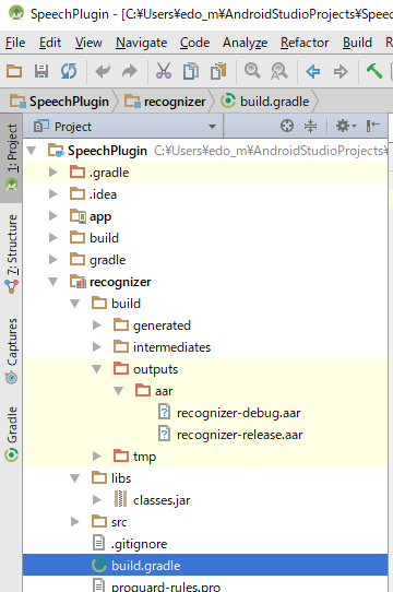
import先はモジュールのlibsフォルダ内です。

なお、該当のファイルは以下の場所にあります。(環境によってパスは読み替えてください)

D:\Program Files\Unity2017.3.1p4\Editor\Data\PlaybackEngines\AndroidPlayer\Variations\mono\Release\Classes\classes.jar

Gradle設定にclasses.jarを含めないよう追記する

classes.jarは、UnitySendMessageを使うのに必要ですが、aarに含まれてしまうとUnityでのビルド時にエラーが出てしまうため、aarに含めないよう設定ファイルに記述する必要があります。

以下を、モジュール用のbuild.gradleに追記します。

android.libraryVariants.all{ variant->
  variant.outputs.each{output->
    output.packageLibrary.exclude('libs/classes.jar')
  }
}

全体としては以下のようになります。

plugins {
    id 'com.android.library'
}

android {
    namespace 'com.edo.speechrecognizer'
    compileSdk 32

    defaultConfig {
        minSdk 23
        targetSdk 32

        testInstrumentationRunner "androidx.test.runner.AndroidJUnitRunner"
        consumerProguardFiles "consumer-rules.pro"
    }

    buildTypes {
        release {
            minifyEnabled false
            proguardFiles getDefaultProguardFile('proguard-android-optimize.txt'), 'proguard-rules.pro'
        }
    }
    compileOptions {
        sourceCompatibility JavaVersion.VERSION_1_8
        targetCompatibility JavaVersion.VERSION_1_8
    }

}

android.libraryVariants.all{ variant->
    variant.outputs.each{output->
        output.packageLibrary.exclude('libs/classes.jar')
    }
}

dependencies {

    implementation 'androidx.appcompat:appcompat:1.5.1'
    implementation 'com.google.android.material:material:1.7.0'
    implementation fileTree(dir: 'libs', include: ['*.aar', '*.jar'], exclude: [])
    testImplementation 'junit:junit:4.13.2'
    androidTestImplementation 'androidx.test.ext:junit:1.1.3'
    androidTestImplementation 'androidx.test.espresso:espresso-core:3.4.0'
}

設定ファイルはこれです。

ちなみに設定しないと、

com.android.build.api.transform.TrasnformException: com.android.idle.common.process.ProcessException: java.util.concurrent.ExecutionException: com.android.dex.DexException: Multiple dex files define Lbitter/jnibridge/JNIBridge$a;

みたいなエラーが出ます。

[2023.03.04 追記]

どうやら上の記述だとビルド時に含まれてしまうようになったっぽいです。
ので、依存関係の解決を以下のように変更します。( compileOnly に変更する)

- implementation fileTree(dir: 'libs', include: ['*.aar', '*.jar'], exclude: [])
+ compileOnly fileTree(dir: 'libs', include: ['*.aar', '*.jar'], exclude: [])

AndroidManifestに録音権限を追記する

当然ですが、音声認識を利用するためにはマイクからの音を利用する必要があるため、AndroidManifestに下記の権限を追記する必要があります。

<uses-permission android:name="android.permission.RECORD_AUDIO" />

Unity側から呼び出す処理を実装する

プラグインが作成できたらそれを利用するためのC#側の実装を行います。
以下のようにしてプラグイン側の処理を呼び出します。

using System.Collections;
using System.Collections.Generic;
using UnityEngine;
using UnityEngine.UI;

public class AndroidSpeechRecognizer : MonoBehaviour
{
    [SerializeField]
    private Text _text;

    private void Update()
    {
        if (Input.touchCount > 0)
        {
            Touch touch = Input.touches[0];
            if (touch.phase == TouchPhase.Began)
            {
                StartRecognizer();
            }
        }
    }

    private void StartRecognizer()
    {
#if UNITY_ANDROID
        AndroidJavaClass nativeRecognizer = new AndroidJavaClass("com.edo.speechplugin.recoginizer.NativeSpeechRecognizer");
        AndroidJavaClass unityPlayer = new AndroidJavaClass("com.unity3d.player.UnityPlayer");
        AndroidJavaObject context = unityPlayer.GetStatic<AndroidJavaObject>("currentActivity");

        context.Call("runOnUiThread", new AndroidJavaRunnable(() =>
        {
            nativeRecognizer.CallStatic(
                "StartRecognizer",
                context,
                gameObject.name,
                "CallbackMethod"
            );
        }));
#endif
    }

    private void CallbackMethod(string message)
    {
        string[] messages = message.Split('\n');
        if (messages[0] == "onResults")
        {
            string msg = "";
            for (int i = 1; i < messages.Length; i++)
            {
                msg += messages[i] + "\n";
            }

            _text.text = msg;
            Debug.Log(msg);
        }
        else
        {
            Debug.Log(message);
        }
    }
}

ネイティブプラグイン側で音声認識の結果をUnitySendMessageによってコールバックするようになっているので、それを受け取るコールバック用メソッドを実装しています。

プラグイン側では文字列でメソッド名を指定してコールバックを実行するので、プラグイン側にメソッド名を適切に渡す必要があります。

あとは認識した文字列を元に、行いたい処理を実装すれば音声認識を利用したアプリを制作することができます。

トラブルシューティング

もし、プラグインは実行できるのにすぐにエラーで停止してしまう場合は、マイクの権限が付与されていない可能性があるのでアプリの設定を見直してみてください。

参考記事

今回のプラグイン作成には以下の記事を参考にさせていただきました。

indie-du.com

fantom1x.blog130.fc2.com

fantom1x.blog130.fc2.com

Unity向けにAndroidのネイティブプラグインを作成する

概要

Unity向けに、Androidのネイティブ機能を呼び出す部分が作りたくて色々調べたのでまとめておきます。

今回は特にこちらの記事を参考にさせていただきました。

indie-du.com

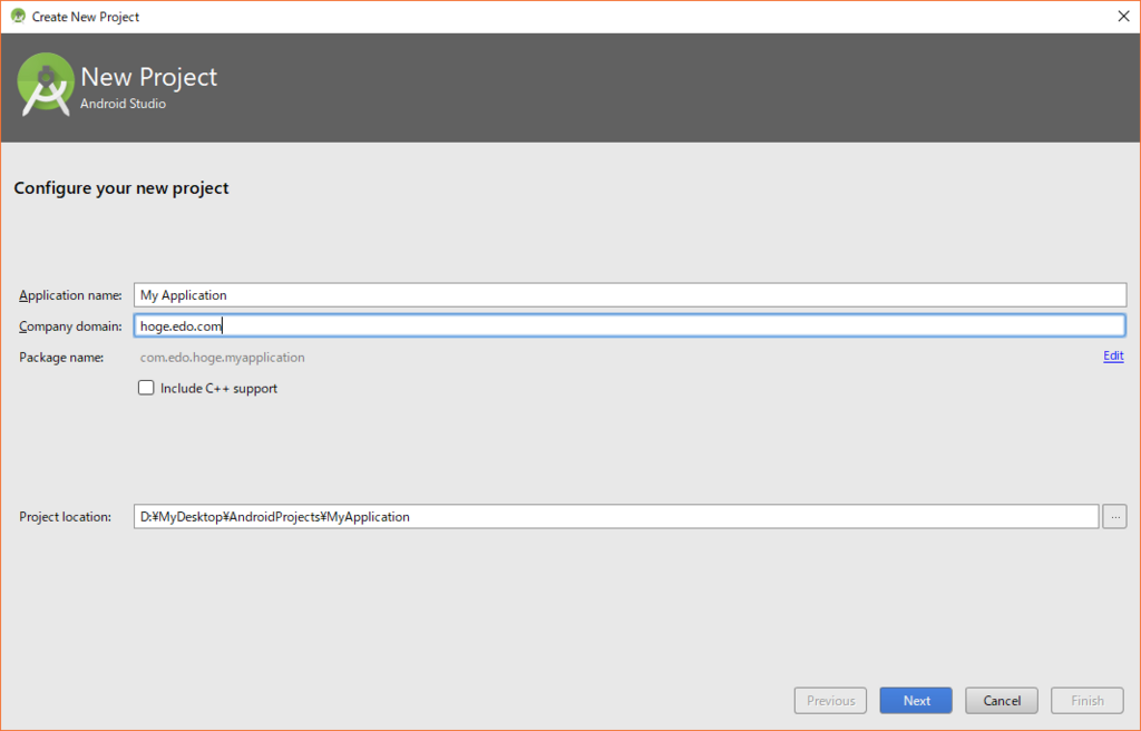
Android Studioで新規プロジェクトを作成する

今回作成するのはaar(Android Archive)なので、新規で作成するプロジェクトは空の、ごくシンプルな状態で作成して問題ありません。(プロジェクト作成後に、モジュール追加してそっちでコードを書くので、通常のapk作成フローとは異なります)

f:id:edo_m18:20180320163214p:plain

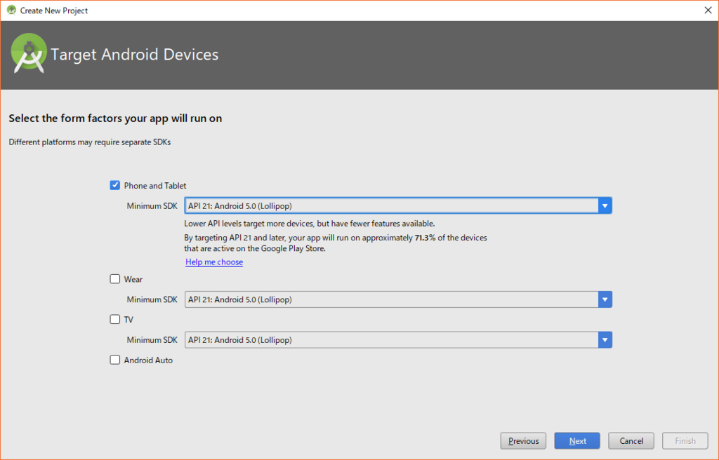
次に、Phone and Tabletを選択し、Minimum SDKのバージョンを設定します。
ここは、後々、Unityの設定でも最低バージョンを指定する際に同じバージョンにしないとエラーが出るので、それなりに小さいのを選んでおいたほうがいいでしょう。

f:id:edo_m18:20180320163359p:plain

そしてAdd No Activityを選択してプロジェクトを作成します。

f:id:edo_m18:20180320163520p:plain

ライブラリ用モジュールを作成する

プロジェクトが作成できたら、ライブラリ用のモジュールを新規追加します。

f:id:edo_m18:20180320163800p:plain

Android Libraryを選択して追加します。

f:id:edo_m18:20180320163843p:plain

プラグイン名となるモジュール名を入力します。

f:id:edo_m18:20180320164033p:plain

すると、プロジェクトビューに、先ほど入力した名前でモジュールが追加されます。

f:id:edo_m18:20180320164210p:plain

Unityからアクセスするクラスを実装する

今回はネイティブの機能(ダイアログ)を簡単に呼び出すだけなので、なにも継承しないシンプルなJavaクラスをモジュールに追加します。
追加するには、Androidビュー内のモジュール名上で右クリックしてNew > Java Classを選択します。

f:id:edo_m18:20180320164823p:plain

そして、NativeDialogというクラス名でファイルを作成し、参考にさせていただいた記事同様の記述を行います。

引用させてもらうと、以下のコードになります。ネイティブのダイアログを表示する、というものです。
パッケージ名は自身の環境に合わせてください

package jp.co.test.dialog_plugin;

import android.app.AlertDialog;
import android.content.Context;

public class NativeDialog {

    static public void showMessage(Context context, String title, String message) {

        new AlertDialog.Builder(context)
                .setTitle(title)
                .setMessage(message)
                .setPositiveButton("YES, YES, YES!", null)
                .setNegativeButton("...No?", null)
                .show();
    }
}

Gradleを使ってビルドする

ファイルが追加されたら、Gradleを使ってビルドします。

Android Studioの右側にある「Gradle」タブを開き、:plugin-name(名称は自身で設定したもの)の下にある「Tasks > build > assemble」をダブルクリックして実行します。

f:id:edo_m18:20180320170330p:plain

基本はこれでビルドされるはずですが、自分の環境ではちょっとエラーで躓いてしまったので、同様のエラーが出た場合は、後述の対策を参照してみてください。

エラー内容

$ Error:A problem occurred configuring project ':hoge-plugin'.
> Could not resolve all dependencies for configuration ':hoge-plugin:_debugPublishCopy'.
   > Could not find any version that matches com.android.support:appcompat-v7:27.+.
     Versions that do not match:
         26.0.0-alpha1
         25.3.1
         25.3.0
         25.2.0
         25.1.1
         + 31 more
     Required by:
         project :dialog-plugin

ビルドが成功すると、プロジェクトフォルダ内(※)の「myplugin/build/outputs/aar」に、ビルドされたaarファイルが作成されています。

Android Studioのプロジェクトビューはいくつかのモードがあり、デフォルトはAndroidになっているので、これをProjectに変更するとフォルダ構造が見れるようになるので、そちらのモードにすると表示されるようになります。

f:id:edo_m18:20180320185855p:plain

上記dialog-pluginというモジュール名で作成した時のキャプチャです。
****-debug.aar****-release.aarが作成されます。今回はdebugのほうをimportしました。

これを、Unityのプラグインフォルダにコピーして利用します。

f:id:edo_m18:20180320170912p:plain

Unityから、ネイティブプラグインの機能を呼び出す

プラグイン部分が作成できたので、あとはこれをC#から読み込み、利用するコードを書きます。
以下のように、AndroidJavaClassAndroidJavaObjectを利用して構築します。

using System.Collections;
using System.Collections.Generic;
using UnityEngine;

public class AndroidDialogTest : MonoBehaviour
{
    private void Update()
    {
        if (Input.touchCount > 0)
        {
            ShowDialog();
        }
    }

    private void ShowDialog()
    {
#if UNITY_ANDROID
        AndroidJavaClass nativeDialog = new AndroidJavaClass("plugintest.edo.com.dialog_plugin.NativeDialog");

        AndroidJavaClass unityPlayer = new AndroidJavaClass("com.unity3d.player.UnityPlayer");
        AndroidJavaObject context = unityPlayer.GetStatic<AndroidJavaObject>("currentActivity");

        context.Call("runOnUiThread", new AndroidJavaRunnable(() =>
        {
            nativeDialog.CallStatic(
                "showMessage",
                context,
                "テスト",
                "ほげ"
            );
        }));
#endif
    }
}

Android Studioのビルドでハマった

Android開発をしている人にとっては多分なんてことはないことなんだと思いますが、Android Studioを使ったことがほぼないので、細かなエラーに悩まされました。

こちらの記事を参考に、ごく簡単なプラグイン作成を試してみたところ、

indie-du.com

以下のようなエラーが。

$ Error:A problem occurred configuring project ':hoge-plugin'.
> Could not resolve all dependencies for configuration ':hoge-plugin:_debugPublishCopy'.
   > Could not find any version that matches com.android.support:appcompat-v7:27.+.
     Versions that do not match:
         26.0.0-alpha1
         25.3.1
         25.3.0
         25.2.0
         25.1.1
         + 31 more
     Required by:
         project :dialog-plugin

どうも調べていくと、Android Support Libraryを最新にしろ、ということのよう。
ただ、調べてもSDK Managerでチェック入れてインストール、みたいなのしか出てこないのに、利用しているAndroid Studioだとそもそもそのチェック項目がない。なんでやねん。

と思っていたら、こちらにやり方が書いてありました。

qiita.com

要は、build.gradleに依存関係を書け、ということのよう。

以下のように追記しました。

allprojects {
  repositories {
    jcenter()
    maven { url 'https://maven.google.com' } // 変更点
  }
}

こちらも参考にさせていただきました。

animane.hatenablog.com

gradle

ちなみに余談ですが、最初、gradle自体が分かっていなかったんですが、ビルド自動化ツールでした。

GradleはApache AntやApache Mavenのコンセプトに基づくオープンソースビルド自動化システムであり、プロジェクト設定の宣言にはApache Mavenが利用するXML形式ではなくGroovyベースのドメイン固有言語 (DSL) を採用している[2]。Gradleはタスクの起動順序の決定に有向非巡回グラフ(英: Directed Acyclic Graph、DAG)を利用する。

[出典: wikipedia]

Android Studioではこれを取り入れていて、専用のタブやビューが存在します。
build.gradleはテキストファイルで、自動ビルドツール用の設定ファイルです。
(なので、プロジェクト内のどこかに存在しているので、それを編集します)

まとめ

以上で、ネイティブのダイアログを表示するだけのプラグインが作成できました。
最後に、全体の流れをまとめとして書いておきます。

  1. Android Studioで空プロジェクトを作る
  2. 作成したプロジェクトにモジュールを新規追加する
  3. モジュールに、ネイティブ機能を実行する処理を追加・実装する
  4. Gradleを使ってモジュールをビルドする
  5. 生成されたaarファイルをUnityにimportする
  6. Unityから、aar内の実装を呼び出す処理を書く

大まかにはこんな流れで実装していきます。
ビルドエラー周りが少々厄介ですが、それをクリアしてしまえば、比較的ネイティブの機能を実行するのは容易になるかなと思います。