概要
今回は「衝突判定編」です。
前回の「流体編」の続編です。
さて、今回は論文で発表されたカールノイズの『衝突判定』について書きたいと思います。
実際に動いている動画↓
やったー。カールノイズの衝突判定もちゃんと動いた。 pic.twitter.com/lMC8pgHjrc
— edom18@AR / MESON (@edo_m18) 2018年6月29日
本題
カールノイズによる流体のような移動表現については前回書きました。
論文によると、これに加えて剛体などの境界を考慮した動きを実現できるそう。
境界による干渉(論文より抜粋)
境界による干渉について、論文では以下のように書かれています。
原文と、それに対する翻訳(Google翻訳+若干の意訳)を併記します。
境界(Boundaries)
Consider a motionless solid object in the flow. The boundary condition viscous flow must satisfy is
.
流れの中に動かないオブジェクトを考えてみる。
その境界条件粘性流はを満たさなければならない。
This can be achieved simply by modulating the potential down to zero with a smoothed step function of distance, so that all the partial derivatives (and hence the curl) of the new potential are zero at the boundary.
これは、距離の平滑化された段階関数を用いてポテンシャルをゼロに変調することでシンプルに達成できる。
つまり、新しいポテンシャルのすべての偏微分(したがってカール)境界でゼロになる。
Of more interest in animation is the inviscid boundary condition,
, requiring that the component of velocity normal to the boundary is zero.
アニメーションで関心があるのは、非粘性境界条件である。
必要なのは、境界に垂直な速度の成分がゼロであることだ。
allowing the fluid to slip past tangentially but not to flow through a solid. Most turbulent fluids have such small viscosities that this is a more reasonable approximation.
流体が接線方向に滑ることを可能にするが、固体を通して流れないようにする。
ほとんどの乱流は、これがより合理的な近似であるような小さな粘性を有する。
In two dimensions, note that our velocity field is just the 90◦ rotation of the gradient ∇ψ: if we want the velocity field to be tangent to the boundary, we need the gradient to be perpendicular to the boundary.
二次元では、速度場は勾配の90°回転に過ぎないことに注意。
速度場を境界線に接したい場合は、境界線に対して垂直な勾配が必要だ。
This happens precisely when the boundary is an isocontour of ψ, i.e. when ψ has some constant value along the boundary.
これは、境界がψの等値であるとき、つまりψが境界に沿ってある一定の値を有するときに正確に起こる。
We can achieve this without eliminating the gradient altogether by modulating ψ with a ramp through zero based on distance to the closest boundary point.
最も近い境界点までの、距離に基いてゼロを通るRampでψを変調することによって、勾配を完全になくすことなくこれを達成できる。
where
is the distance to all solid boundaries and
is the width of the modified region—when using noise with length scale L, it makes sense to set
. We use the following smooth ramp:
は、すべてのソリッド境界までの距離であり、
は修正された領域の幅である。
長さスケールのノイズを使用する場合、
に設定することは理にかなっている。
次の、平滑化Ramp関数を利用する:
In three dimensions things are a little more complicated.
3次元の場合はもう少し複雑だ。
be the normal to the boundary at the closest point to
, we use
は
に最も近い点の境界の法線である。
したがって、次の式を使う。
That is, we ramp down the tangential component of
near the boundary, but leave the normal component unchanged. This can be proven to give a tangential velocity field at smooth object boundaries, using the fact that
is the gradient of signed distance from the boundary (hence its curl vanishes).
つまり、の接線成分を境界付近で下降(ramp down)させるが、通常の成分は変化させない。
これは、nが境界からの符号付き距離の勾配であるという事実を利用して、滑らかなオブジェクト境界で接線方向の速度場を与えることが証明される。
(したがってそのカールは消える)
Unfortunately, the normal field may be discontinuous along the medial axis of the geometry: na¨ıvely using equation (5) can result in spikes when we take the curl, particularly near sharp edges.
残念なことに、通常のフィールドは、ジオメトリの内側軸に沿って不連続である可能性がある。
式(5)を使用すると、カールを取るとき、特に鋭いエッジ付近でスパイクが発生する可能性がある。
This isn’t a problem for equation (3) since the distance field is Lipschitz continuous, which is adequate for our purposes.
これは、距離場がLipschitz連続であるため、式(3)の問題ではない。
これは、目的に対して適切である。
Thus within distance
of edges flagged as sharp in the system we default to (3), i.e. drop the normal component.
したがって、システム内でシャープとフラグ立てられたエッジの距離d0内では、デフォルトで(3)になる。
すなわち、通常の成分を落とす。
さて、初見ではなんのこっちゃですが、(自分の浅い理解では)要するに、境界付近では接線方向にのみ速度を持たせてやることで、そちらに流れていくよね、ということを言いたいのだと思います。
そのことを示す式が以下です。
(拘束)が示すように、境界付近での速度の方向を拘束し、流れを変えることを表す式です。
もう少し具体的に見てみましょう。
式の右辺を見ると、に対してなにやら計算しています。
このはポテンシャル、つまりカールノイズの計算部分です。
その得られた速度ベクトルに対してなにやら計算しているわけです。
式を少し簡単にしてみると、(を
と置きます)
ということです。
つまり、なんらかの係数に応じて徐々にそちらのベクトルを採用する、いわゆる線形補間的な計算ですね。
ただ、右側に置かれているほうはもう少し複雑で、正確には以下です。
ただ、これも分解して考えると、いわゆる「法線方向ベクトルにどれだけ沿っているか」の計算です。
一般的な計算に書き直してみると、
ですね。
コードで表してみる
さて、上記の部分をコードで表したのが以下になります。
境界の法線を計算する
式では、境界付近の法線を利用しています。
そして法線の計算は以下のようになります。
// 勾配(gradient)を計算する
// 基本的な考えは偏微分が法線ベクトルとなることを利用している?
float3 ComputeGradient(float3 p)
{
    const float e = 0.01f;

    // 偏微分するため、各軸の微小値を計算する
    const float3 dx = float3(e, 0, 0);
    const float3 dy = float3(0, e, 0);
    const float3 dz = float3(0, 0, e);

    float d = SampleDistance(p);
    float dfdx = SampleDistance(p + dx) - d;
    float dfdy = SampleDistance(p + dy) - d;
    float dfdz = SampleDistance(p + dz) - d;

    return normalize(float3(dfdx, dfdy, dfdz));
}

// 計算点から、障害物への距離を計算する
float SampleDistance(float3 p)
{
    float3 u = _SphereParam.xyz - p;
    float d = length(u);
    return d - _SphereParam.w;
}
なぜ偏微分したらそれが法線ベクトルになるのかについては以下を参照。
また、距離関数については、(今回は)単純なSphereのみとしているので、比較的シンプルな式で距離計算が出来ています。
その他の距離関数については、こちらのサイトを参照ください。
modeling with distance functions
そして、ポテンシャルの計算を行っているコードが以下。
// α = ramp(d(x)/d0)
// ψ_constrainted(x) = αψ(x) + (1 - α)n(n・ψ(x))
float3 SamplePotential(float3 pos, float time)
{
    float3 normal = ComputeGradient(pos);
    float distance = SampleDistance(pos);

    float3 psi = float3(0, 0, 0);

    // 高さに応じて乱流の度合いを変化させる(上にいくほど拡散するように)
    float heightFactor = Ramp((pos.y - _PlumeBase) / _PlumeHeight);
    for (int i = 0; i < 3; i++)
    {
        float alpha = Ramp(abs(distance) / _NoiseScales[i]);

        float3 s = pos / _NoiseScales[i];

        float3 psi_i = Constraint(Pnoise(s), normal, alpha);
        psi += psi_i * heightFactor * _NoiseGain[i];
    }

    float3 risingForce = _SphereParam.xyz - pos;
    risingForce = float3(-risingForce.z, 0, risingForce.x);

    // ringの半径?
    // XZ平面の中心からの半径? RingRadius?
    float rr = sqrt(pos.x * pos.x + pos.z * pos.z);
    float temp = sqr(rr - _RingRadius) + sqr(rr + _RingRadius) + _RingFalloff;
    float invSecond = 1.0 / _RingPerSecond;
    float ringY = _PlumeCeiling;
    float alpha = Ramp(abs(distance) / _RingRadius);

    // 「煙の柱(Plume)」の下端以下になるまで繰り返す
    while (ringY > _PlumeBase)
    {
        // ringの位置とパーティクルのYの差分
        float ry = pos.y - ringY;

        float b = temp + sqr(ry);
        float rmag = _RingMagnitude / b;

        float3 rpsi = rmag * risingForce;
        psi += Constraint(rpsi, normal, alpha);
        ringY -= _RingSpeed * invSecond;
    }

    return psi;
}
なお、上記コードの乱流生成部分は以下の記事を参考にさせてもらいました。
カールノイズを実装したコンピュートシェーダ全文はこちら↓
論文翻訳メモ
さて、最後に、論文を理解するにあたってちょいちょい(Google翻訳などを利用しながら)翻訳していったものがあるので、せっかくなのでメモとして残しておこうと思います。
※ 注意! いくらかは自分の意訳部分があるので、完全な翻訳ではありません。
速度は、ポテンシャル(ベクトル場)()に対して回転(curl)をかけたものとして得られる。
カールされたベクトル場は自動的にダイバージェンスフリーとなる。
A classic vector calculus identity is that the curl of a smooth potential is automatically divergence-free
よって、
パーリンノイズを使ってベクトル場を形成する。
2Dの場合は、単純に。
To construct a randomly varying velocity field we use Perlin noise
in our potential. In 2D, [tex:]\psi = N].
3Dの場合は、3要素(ベクトル)が必要となるが、同じノイズ関数を、明らかに大きなオフセットをかけた入力ベクトルを用いて表現する。
普段は、いくつかの異なったスケールを使ったオクターブノイズを乱流の形成のために使う。
In 3D we need three components for the potential: three apparently uncorrelated noise functions (a vector
) do the job, which in practice can be the same noise function evaluated at large offsets.
3Dの場合は、速度ノイズの接線成分のみ、ゼロに減少する。
In 3D, only tangential components of vector noise are ramped down.
シーン内のオブジェクトからゼロに減衰するか、または煙の列の高さに応じて変化させる。
decay to zero away from objects in the scene, or changing it according to the height in a column of smoke.
速度場 はもはやdivergence-freeを与えないが、それにカールのトリックで成す。
While simply modulating the velocity field
no longer gives a divergnce-free field, modulating the potential,
, does the trick.
他のポテンシャル(Other Potentials)
これまでは、動かない境界線に対するノイズだけを構築してきた。
もちろん、既存のプリミティブのフローを速度場に使って、よりリッチな機能を実現することもできる。
そして、ポテンシャルをより高めることができる。
So far we have only constructed noise that respects unmoving solid boundaries. While of course we can superimpose existing flow primitives on the velocity field for richer capabilities, we can also do more with the potential itself.
線形速度と角速度
を持つRigidbodyに対応するポテンシャルを導出することはシンプルにできる。
It is simple to derive a potential corresponding to a rigid body motion with linear velocity
and angular velocity
:
ここで、は任意の参照点であり、
は任意の参照レベルを表す。
where
is an arbitrary reference point and R is an arbitrary reference level.
Note:
同じに対応する無限に多くのポテンシャルが常に存在することに気をつける。
スカラー場の勾配だけが異なるふたつのポテンシャルは、同じカールを有する。
Note that there are always infinitely many potentials corresponding to the same
: any two potentials which differ by only the gradient of some scalar field have exactly the same curl.
動くRigidbodyの境界条件を満たすように修正したポテンシャルを仮定する。
まず、物体の表面上速度の法線成分をゼロにするために方程式(5)を使用し、を与える。
次に、を剛体の中心として選択した式(6)を使用し、オブジェクトからゼロに滑らかにブレンドする。
(をブレンド領域の半径とすると、ブレンドされた回転項が単調に0に落ちる)
Suppose we have a potential
we wish to modify to respect boundary conditions on a moving rigid object. First we use equation (5) to zero out the normal component of velocity on the object’s surface, giving
. Then we use equation (6) with
chosen, say, as the center of the rigid body, smoothly blend it to zero away from the object (choosing R to be the radius of the blend region, so that the blended rotational term drops monotonically to zero),
それを加えて
を得る。
例えば、各剛体への逆二乗距離に基づくブレンド関数の実験を行った。
We have experimented, for example, with a blending function
based on inverse squared distance to each rigid body.
剛体の境界では、速度は剛体モーションと、表面に接するベクトル場の合計となる。
これは構成上、非粘性境界条件を尊重する。
Note that at the boundary of the rigid object, the velocity is the sum of the rigid motion and a vector field tangent to the surface: by construction this respects the inviscid boundary condition.
単一のボディにてついては参照点は任意だが、複数のボディがある場合は同じ参照点を使用してブレンドをよりよくするのに役立つ。
特に、すべてのボディが同じ剛体モーションで動いている場合は、そのポテンシャルを合わせてブレンドを完璧にしたいと考えている。
While for a single body the reference point is arbitrary, if we have multiple bodies it can help to use the same reference point to make the blend better. In particular, if all bodies are moving with the same rigid motion, then of course we want their potentials to match up to make the blend perfect.
変形する物体の周りの流れ場はよりトリッキーである。
閉じた変形表面の場合、もしボディがその体積を保持しなければ不可能である。
したがって、将来の作業のためにそれは残しておく。
Flow fields around deforming bodies are trickier. For a closed deforming surface, it may even be impossible—if the body doesn’t conserve its volume—and thus we leave that for future work.
いくつかのプリミティブな渦(Vortex)は、位置の角速度
、半径
、および平滑化フォールオフ関数を有する単純なパーティクルを含む。
Some vortex primitives include a simple vortex particle at
with angular velocity
, radius
, and smooth fall-off function
:
そして、スモーク・リングやプルーム(Plumes)に役立つ、単純な渦カーブ:
and a simple vortex curve, useful for smoke rings and plumes:
は
までの、曲線上の最も近い点であり、
は角速度(曲線に接する)である。
他の興味深いフロー構造も、剛体運動式を念頭に置いて同様に作成することができる。
where
is the closest point on the curve to
, and
C is the angular velocity (tangent to the curve). Other interesting flow structures can be similarly created with the rigid motion formulas in mind.
備考メモ
論文に書かれている備考部分に対するメモです。(あくまで個人的な解釈です)

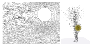
↑論文に添えられていた図
左手側は、剛体の背後に乱流を起こしたもの。右手側は、流体を後ろに押し出したあと渦輪を設定したもの。(あってる?)
どちらのケースも、乱流ノイズの各オクターブは、ジオメトリに対してスケールに適した方法で調整される。
そして、障害物の背後にのみ生成した乱流に平滑化された振幅関数を乗算する。
これを、基礎の層流(lamninar(ラミナ))に加える。これも、境界付近でスムーズにゼロにランプされる。
※ 流体の流れは2つに分けられ、流体部分が秩序正しく流れる場合を層流と呼び、不規則に混合しながら流れる場合を乱流と呼ぶ。
出典: https://www.weblio.jp/content/laminar+flow
個人的見解
以下は、論文を読んでいくにあたって、記号など「こういう意味かなー」と思ったことのメモです。
記号や単語の意味を類推して読んでいくと意外とすっと頭に入ってくることもあるので。
が、乱流(Trubulent)を表す式。(なので
)
それを、ジオメトリに応じてAdjustする変数。
これが「乱流」部分になるので、それを、基礎層流(Laminar Flow)に加える、ということになる。
(という意味かな?)
そして、基礎層流を表すのが
の式。
仮にこれをと置き、さらに乱流を
と置くと、最後の式は
と書ける。
このが、文章で書かれている「We then multiply by a smooth AMPLITUDE function」のことだと思う。
ただ、平滑化された振幅関数ってどう表現するのだろう・・。ひとまず適当にSinとか掛けておけばいいんだろうか。
なんとなく、Sinを使った値を加算してみたら煙が立ち上る感じに見えたので、多分そんな感じなんだと思うw
その他、役立ちそうなリンク
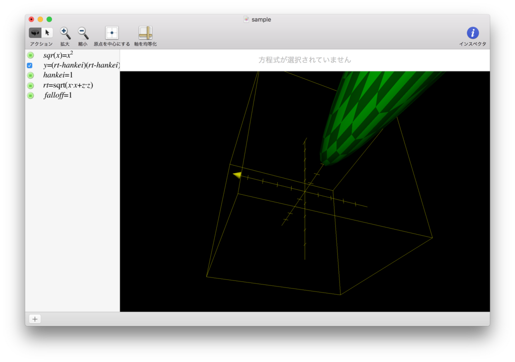
リンクではありませんが、MacにはGrapherというアプリが標準でついていて、以下のキャプチャのように、数式を入れるとそれを可視化してくれる、というものがあります。
数式だけだと一体なにをしているんだ? となることが多いですが、視覚化されると「ああ、なるほど。こういう形を求めているのだな」と分かることが少なくないので、利用して色々な数式を視覚化してみることをオススメします。
